 |
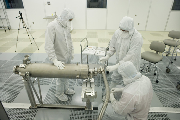
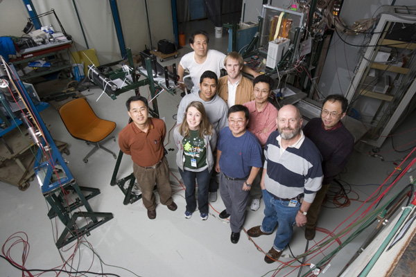
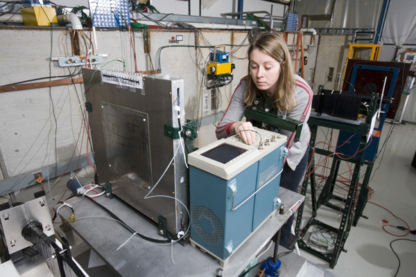
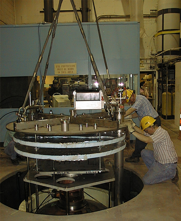
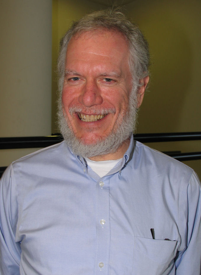
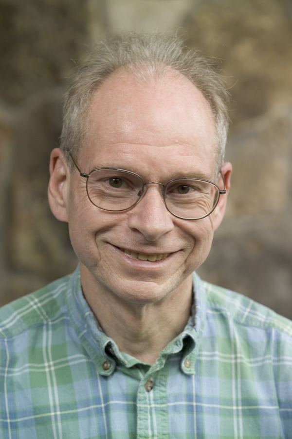
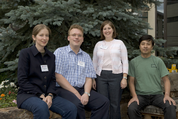
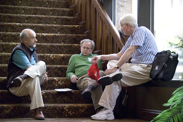
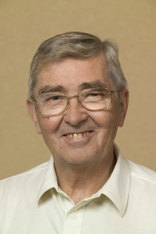
Many of the SLAC and Stanford researchers who helped create the accelerator on a chip are pictured in SLAC's NLCTA lab where the experiments took place. Left to right: Robert Byer, Ken Soong, Dieter Walz, Ken Leedle, Ziran Wu, Edgar Peralta, Jim Spencer and Joel England. (Courtesy: Matt Beardsley/SLAC) |
||
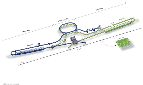 |
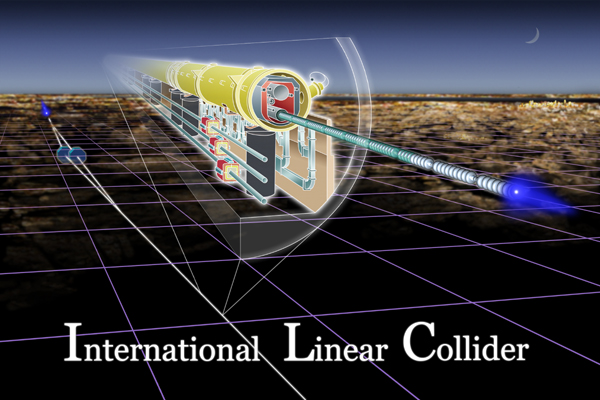
International Linear Collider conceptual diagram - Next-generation particle accelerator (Courtesy: ILC GDE) |
||
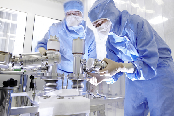 |
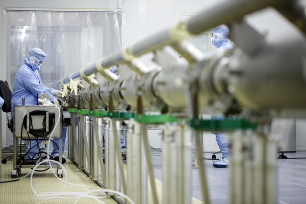
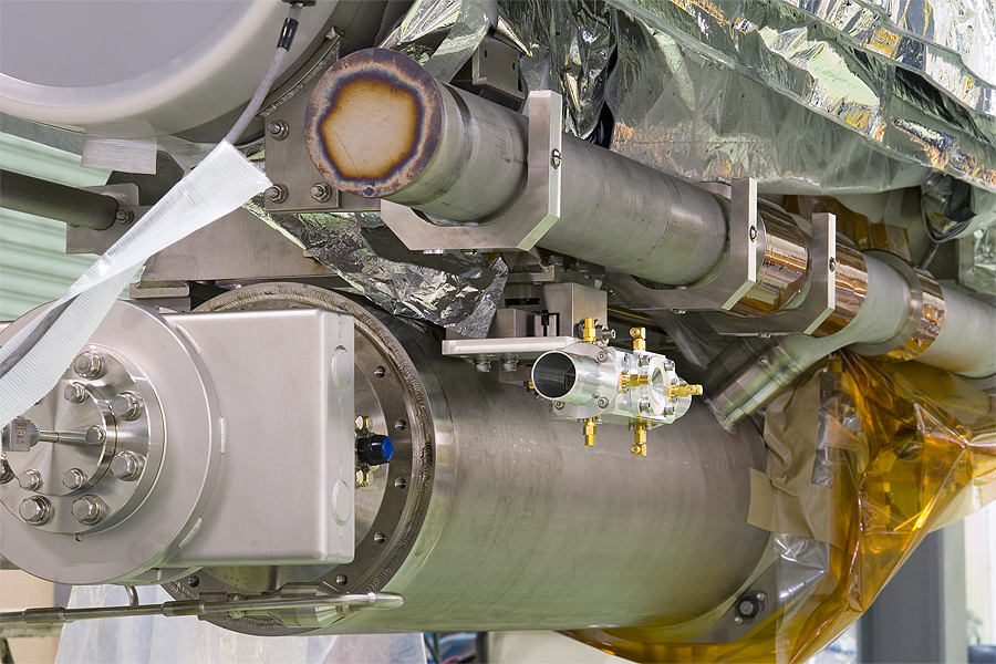
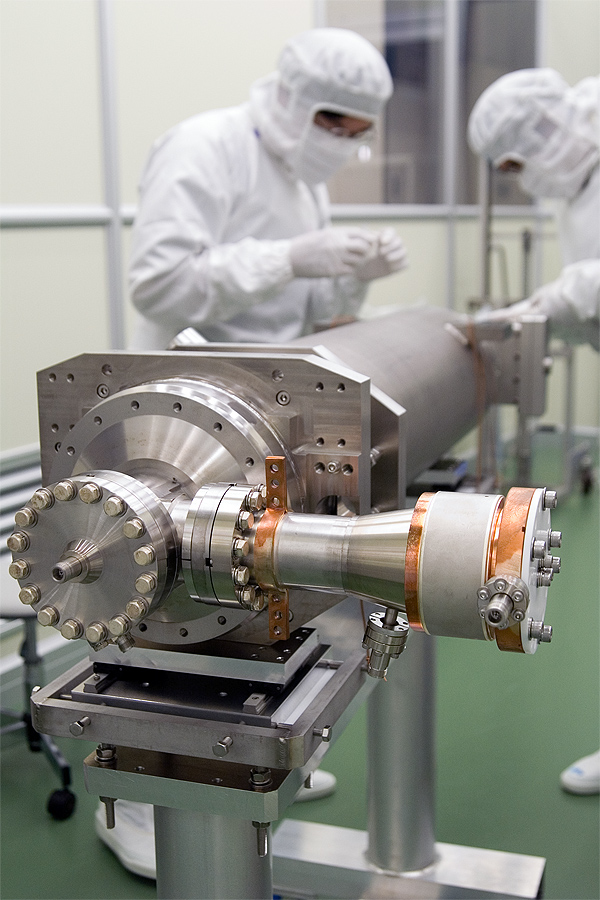
These couplers, built at the French laboratory LAL in Orsay, feed the high frequency into the cavities. Cleanroom: LAL, Orsay. Part of the “Life of a cavity” image series. (Image courtesy of DESY/ILC, photographer: Heiner Müller-Elsner) |
||
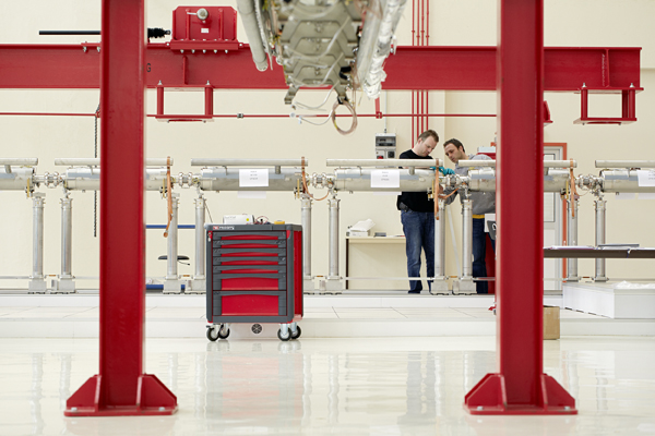 |
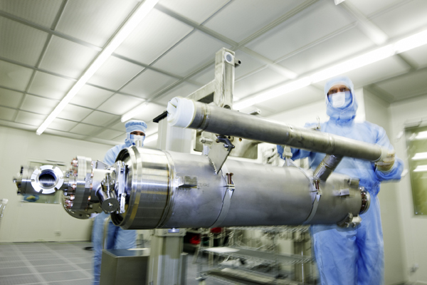
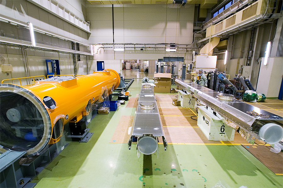
When all cavities, tanks and pipes have been connected and sealed in the cleanroom, the string is inserted into a cryomodule. Here: CEA, Saclay, France. Part of the “Life of a cavity” image series. (Image courtesy of DESY/ILC, photographer: Heiner Müller-Elsner) |
||
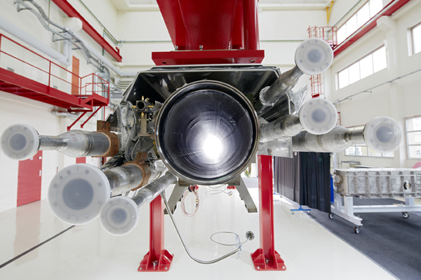 |
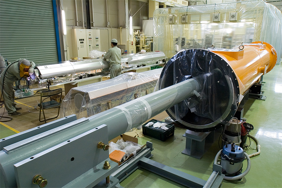
The gaseous helium is returned through this pipe. The cavity string is later attached to this construction before it is inserted into the cryomodule. Here: CEA, Saclay, France. Part of the “Life of a cavity” image series. (Image courtesy of DESY/ILC, photographer: Heiner Müller-Elsner) |
||
 |
The cavity’s final home: the cryomodule. Eight cavities sit in one module, and depending on the accelerator there may be some hundred or more than a thousand of these cryomodules connected to each other in a row. Here: CEA, Saclay, France. Part of the “Life of a cavity” image series. (Image courtesy of DESY/ILC, photographer: Heiner Müller-Elsner) |
||
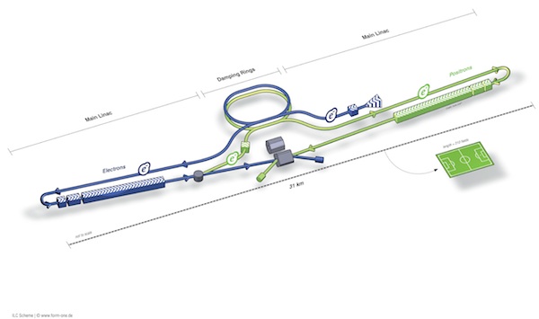 |
A schematic layout of the International Linear Collider. (Graphic courtesy of ILC / form one visual communication) |
||
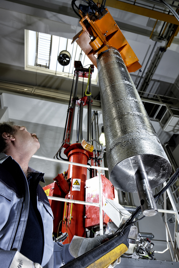 |
A niobium ingot is lowered into the electron beam melting oven at the German company Heraeus. The melting process turns the already pure niobium into the highly purified material needed for cavity production. Part of the “Life of a cavity” image series. (Image courtesy of DESY/ILC, photographer: Heiner Müller-Elsner) |
||
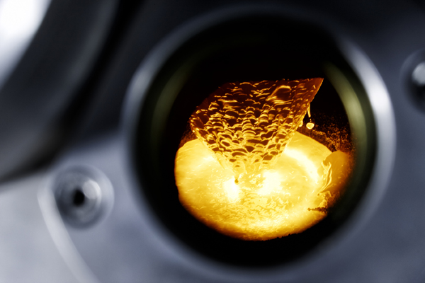 |
When liquid niobium drips off the ingot in the electron beam melting oven at Heraeus, all other gases and impurities vanish. Part of the “Life of a cavity” image series. (Image courtesy of DESY/ILC, photographer: Heiner Müller-Elsner) |
||
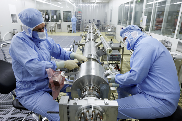 |
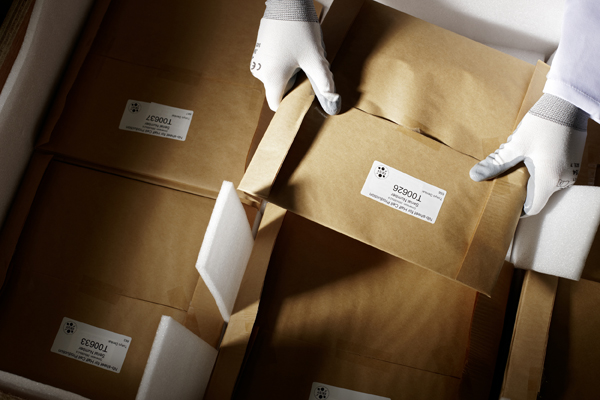
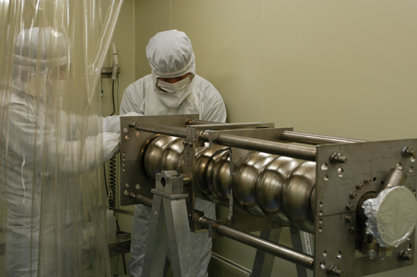
Eight cavities in their helium tank and all other necessary equipment are assembled into a cavity string. This requires extreme precision and extreme cleanliness. Cleanroom: DESY. Part of the “Life of a cavity” image series. (Image courtesy of DESY/ILC, photographer: Heiner Müller-Elsner) |
||
 |
Eight cavities in their helium tank and all other necessary equipment are assembled into a cavity string. This requires extreme precision and extreme cleanliness. Cleanroom: DESY. Part of the “Life of a cavity” image series. (Image courtesy of DESY/ILC, photographer: Heiner Müller-Elsner) |
||
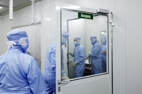 |
Change of shift in the cleanroom. After passing a series of quality and performance tests, cavities are assembled into strings in the cleanroom. Cleanroom: DESY. Part of the “Life of a cavity” image series. (Image courtesy of DESY/ILC, photographer: Heiner Müller-Elsner) |
||
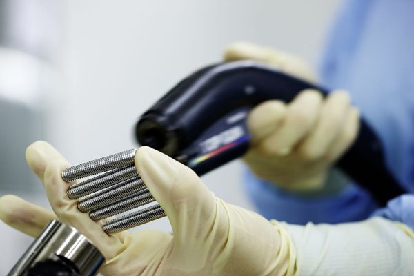 |
Every little detail in the cleanroom needs to absolutely dust-free. An air pistol blows extremely clean air over the screws and a particle counter registers how many dust particles fly off it. Cleanroom: DESY. Part of the “Life of a cavity” image series. (Image courtesy of DESY/ILC, photographer: Heiner Müller-Elsner) |
||
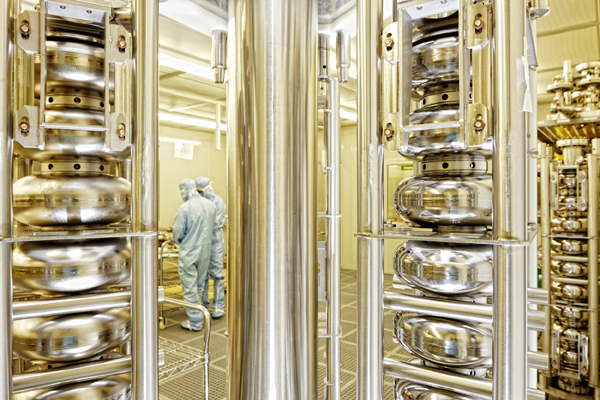 |
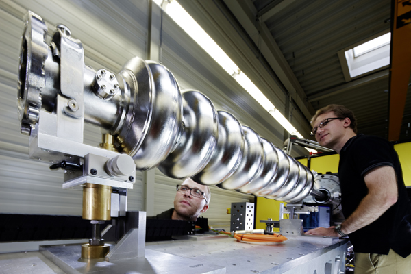
The tried and tested nine-cell cavities are standing ready for assembly. Cleanroom: DESY. Part of the “Life of a cavity” image series. (Image courtesy of DESY/ILC, photographer: Heiner Müller-Elsner) |
||
 |
The cavity has disappeared into a helium tank. During operation it sits in a bath of liquid helium which cools it down to almost absolute zero – a prerequisite for superconductivity. Cleanroom: DESY. Part of the “Life of a cavity” image series. (Image courtesy of DESY/ILC, photographer: Heiner Müller-Elsner) |
||
 |
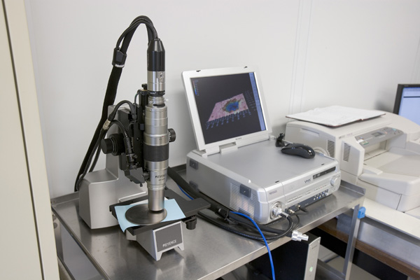
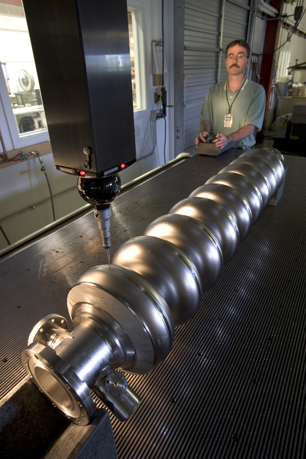
A robot with a specially designed and programmed camera checks whether the welding seams may have the potential of causing a quench and what the inner surface of the cavity looks like. Part of the “Life of a cavity” image series. (Image courtesy of DESY/ILC, photographer: Heiner Müller-Elsner) |
||
 |
Only few companies around the world are qualified to turn the niobium into sheets. Which form the basis of the cavities’ cells. Part of the “Life of a cavity” image series. (Image courtesy of DESY/ILC, photographer: Heiner Müller-Elsner) |
||
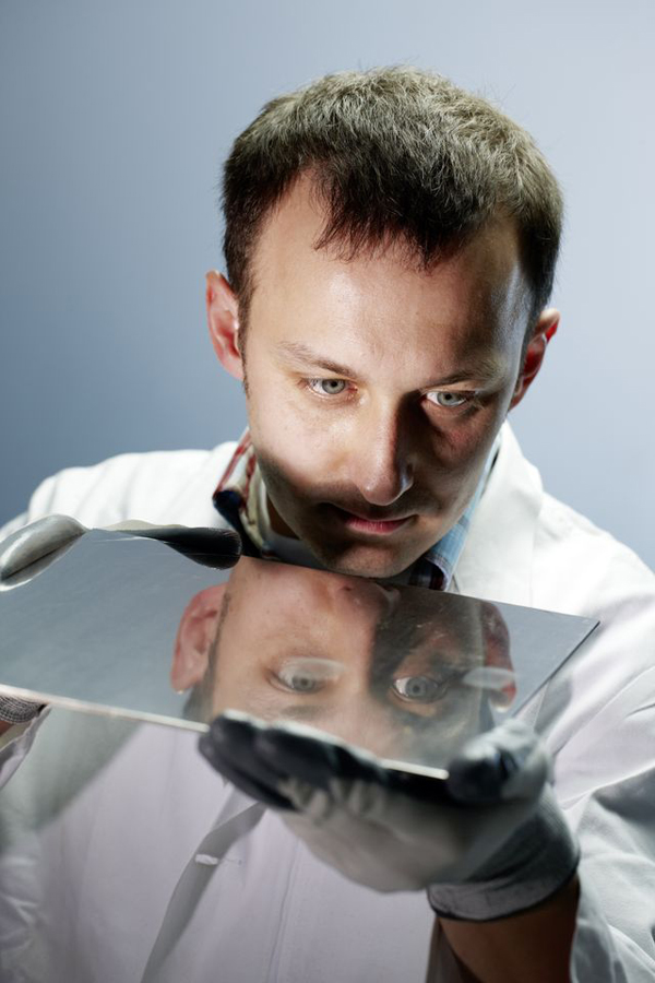 |
The surface of the niobium sheets is inspected by eye at DESY, Germany. Part of the “Life of a cavity” image series. (Image courtesy of DESY/ILC, photographer: Heiner Müller-Elsner) |
||
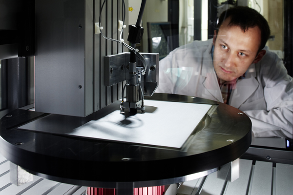 |
A scanning machine at DESY scans the niobium sheet for material defects. It can find faults down to 0.1 millimetre in size. Part of the “Life of a cavity” image series. (Image courtesy of DESY/ILC, photographer: Heiner Müller-Elsner) |
||
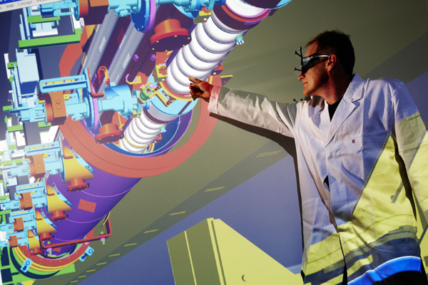 |
Latest virtual-reality technology in DESY’s 3-D lab makes it possible to walk through the accelerator before it’s built. Part of the “Life of a cavity” image series. (Image courtesy of DESY/ILC, photographer: Heiner Müller-Elsner) |
||
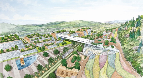 |
Future city of the ILC. Architect's view of an international science research city. (Courtesy: K. Mori and K. Hayakawa) |
||
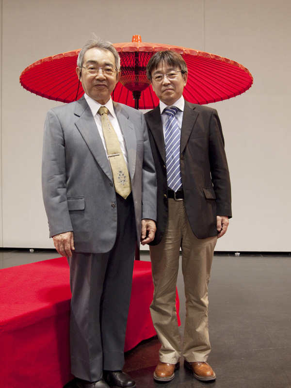 |
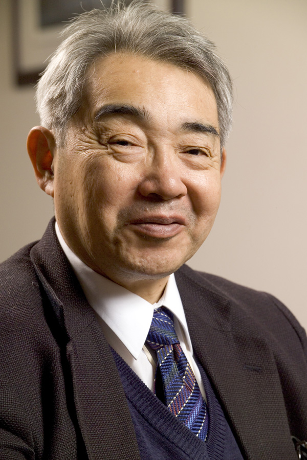
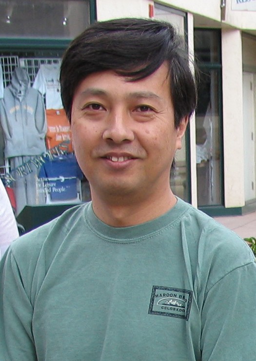
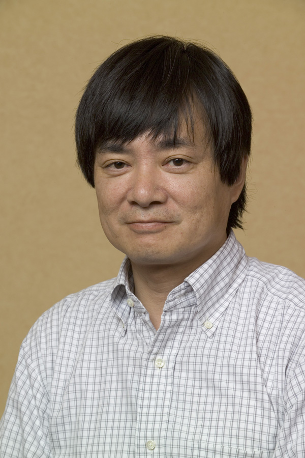
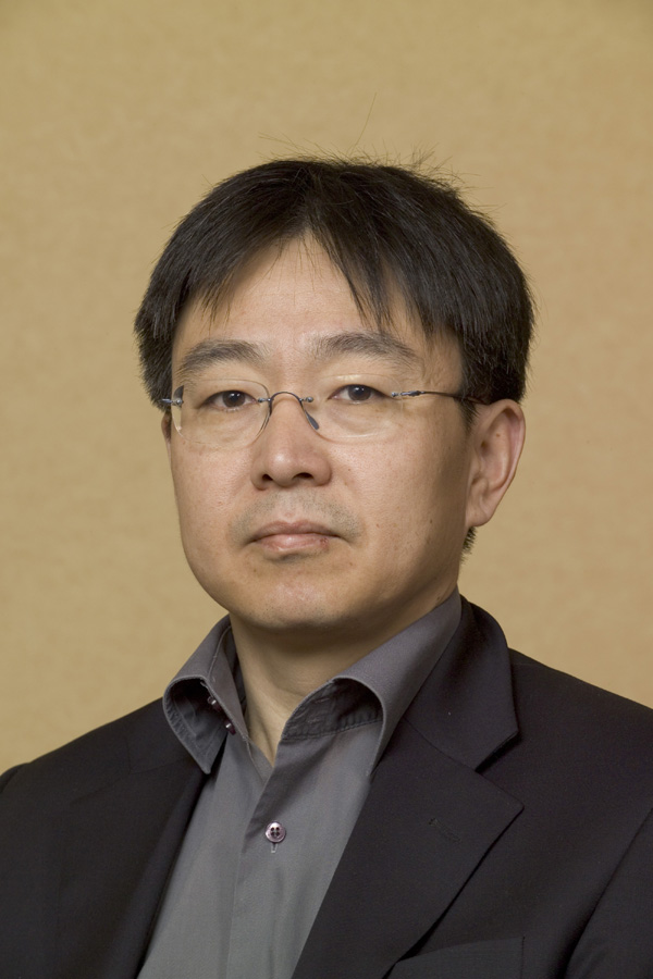
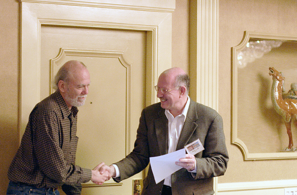
Former and new Asian Linear Collider Steering Committee (ALCSC) chair, Shin-ichi Kurokawa (left) and Jie Gao (right), meet at the First International Particle Accelerator Conference (IPAC'10) conference at Kyoto on May 2010. (Courtesy: Nobuko Kobayashi) |
||
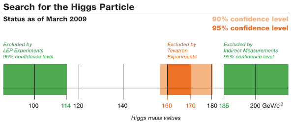 |
Scientists from the CDF and DZero collaborations at DOE's Fermilab have combined Tevatron data from their two experiments to increase the sensitivity for their search for the Higgs boson. While no Higgs boson has been found yet, the results announced today exclude a mass for the Higgs between 160 and 170 GeV/c² with 95 percent probability. A larger area is excluded at the 90 percent probability level. Earlier experiments at the Large Electron-Positron Collider at CERN excluded a Higgs boson with a mass of less than 114 GeV/c² at 95 percent probability. Calculations of quantum effects involving the Higgs boson require its mass to be less than 185 GeV/c². The results show that CDF and DZero are sensitive to potential Higgs signals. The Fermilab experimenters will test more and more of the available mass range for the Higgs as their experiments record more collision data and as they continue to refine their experimental analyses. (Courtesy: Fermilab) |
||
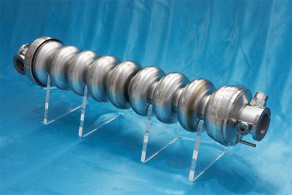 |
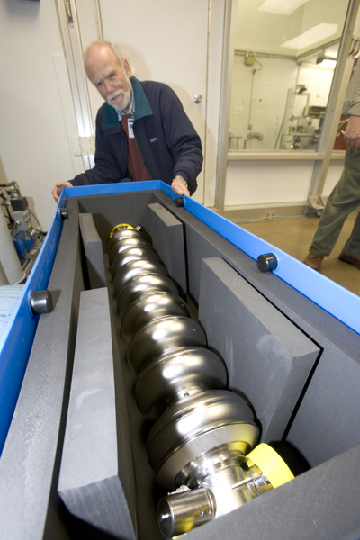
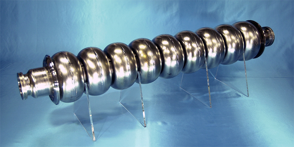
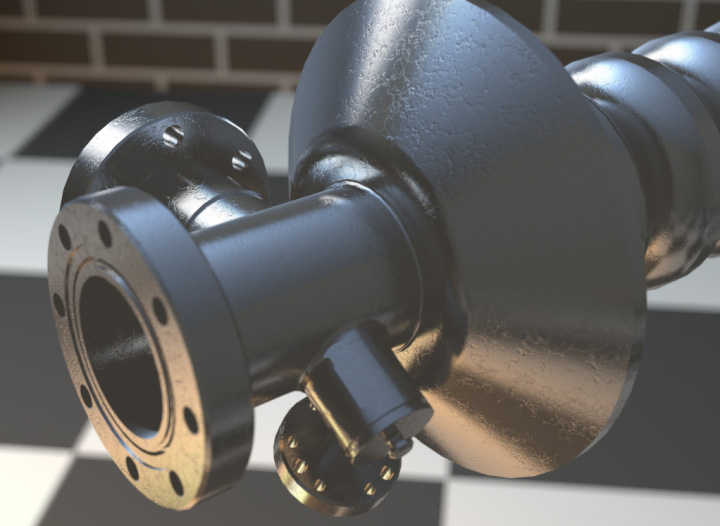
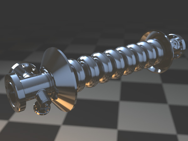
Tesla-like accelerator cavity (Courtesy of Nobu Toge) |
||
 |
Ralph Colon inspects one of the 33 undulator magnets designed for SLAC's Linac Coherent Light Source. (Courtesy SLAC) |
||
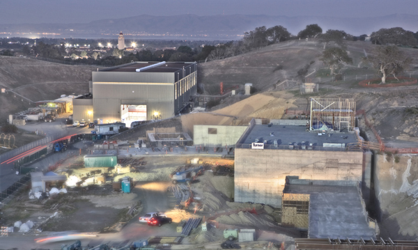 |
Looking east over the LCLS construction site toward Stanford University and the San Francisco Bay. (Courtesy: SLAC) |
||
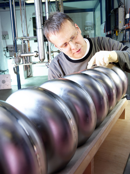 |
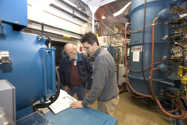
DESY accelerator physicist Lutz Lilje inspecting a TTF cavity (Credit DESY, photo: Christian Schmid) |
||
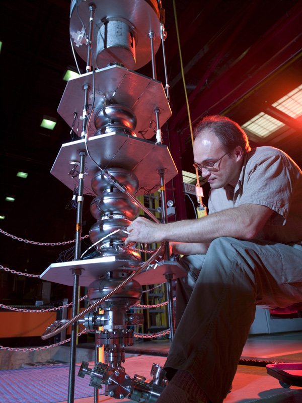 |
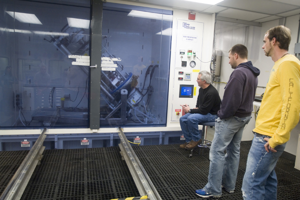
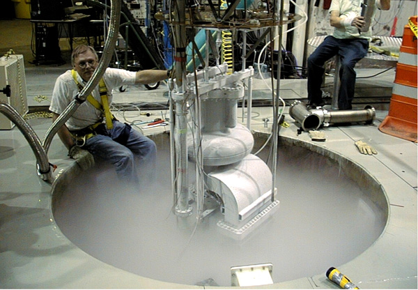
Scientists prepare a superconducting cavity for a test in Fermilab's Vertical Test Stand. (Courtesy Fermilab Visual Media Services) |
||
 |
Scientists prepare a superconducting cavity for a test in Fermilab's Vertical Test Stand. (Courtesy Fermilab Visual Media Services) |
||
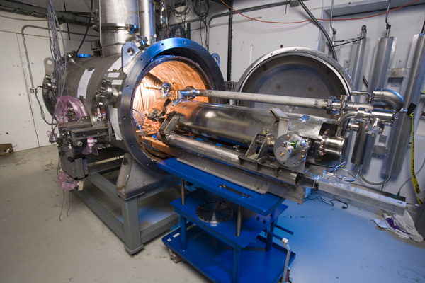 |
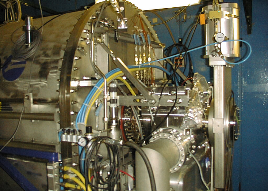
Dressed Superconducting ILC Cavity insertion in Horizontal Test Stand at Meson Building. (Courtesy Fermilab Visual Media Services) |
||
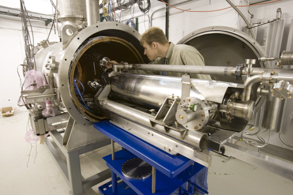 |
Dressed Superconducting ILC Cavity insertion in Horizontal Test Stand at Meson Building. (Courtesy Fermilab Visual Media Services) |
||
 |
Dressed Superconducting ILC Cavity insertion in Horizontal Test Stand at Meson Building. (Courtesy Fermilab Visual Media Services) |
||
 |
International Linear Collider ( ILC ) cavity preparation in clean room at MP9. (Courtesy Fermilab Visual Media Services) |
||
 |
International Linear Collider ( ILC ) cavity preparation in clean room at MP9. (Courtesy of Fermilab Visual Media Services) |
||
 |
International Linear Collider ( ILC ) Beam Test at Meson Lab. (Courtesy Fermilab Visual Media Services) |
||
 |
International Linear Collider ( ILC ) Beam Test at Meson Lab- Jacob Smith and Carlos Medina. (Courtesy Fermilab Visual Media Services) |
||
 |
International Linear Collider ( ILC ) Beam Test at Meson Lab - Heather Brown. (Courtesy Fermilab Visual Media Services) |
||
 |
International Linear Collider ( ILC ) Beam Test at Meson Lab - Seongtae Park. (Courtesy Fermilab Visual Media Services) |
||
 |
Artist's impression of the SiD detector concept for the ILC. (Graphic courtesy of Norman Graf, SLAC/Sandbox Studio) |
||
 |
Artist's impression of the interaction region, where the electrons and positrons would collide, inside the International Linear Collider. (Credit: Greg Stewart, SLAC) |
||
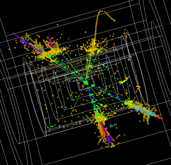 |
A simulation of what the decay of a Z + Higgs to four jets would look like in an ILC detector. (Image courtesy of Norman Graf) |
||
 |
Participants at the ILC DR07 (Meeting on Damping Ring R&D) at Frascati, Italy, 5 to 7 March 2007. (Courtesy of INFN) |
||
 |
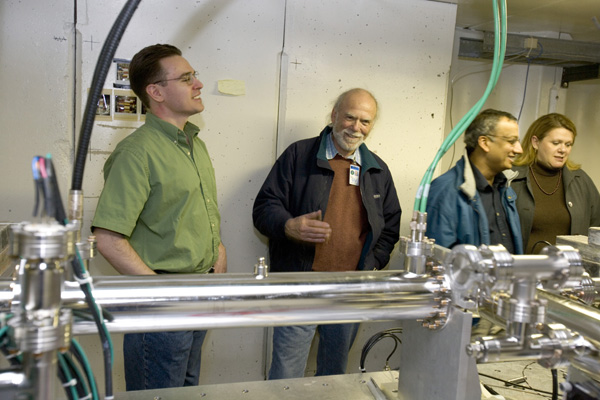
(L-R) John Mammosser (JLab), Cristian Boffo (Fermilab) and Damon Bice (Fermilab) look on during an electropolishing session of an ILC cavity. (Photo Credit: Greg Adams, DOE's Jefferson Lab) |
||
 |
Artist's rendition of a particle event inside the International Linear Collider. (Credit Sandbox Studio) |
||
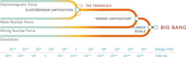 |
Energy scale (Credit: Sandbox Studio) |
||
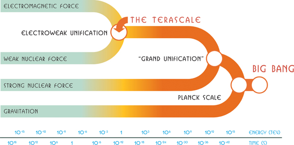 |
Energy scale (Credit: Sandbox Studio) |
||
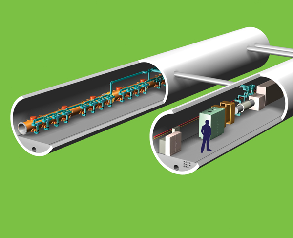 |
Artist's impression of the ILC tunnels. (Graphic courtesy of Fermilab/Sandbox Studio) |
||
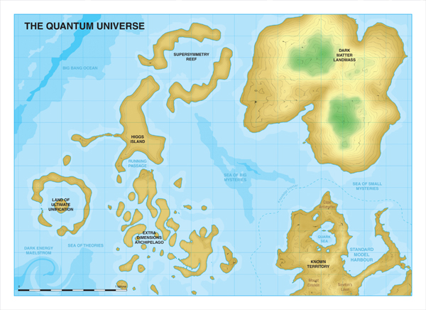 |
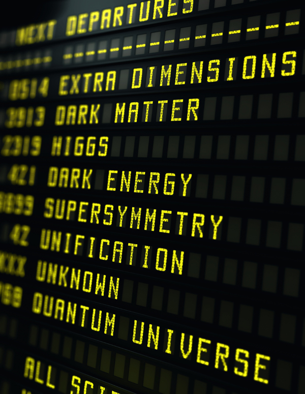
Artist’s impression of a map of the Quantum Universe, highlighting the discovery scenarios of the International Linear Collider. (Graphic courtesy of ILC / form one visual communication) |
||
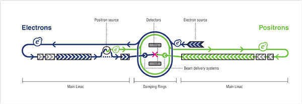 |
A schematic layout of the International Linear Collider. (Graphic courtesy of ILC / form one visual communication) |
||
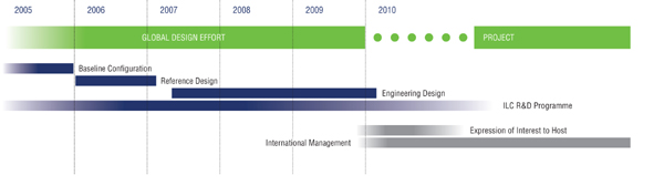 |
A technical timeline for the International Linear Collider. (Graphic courtesy of ILC / form one visual communication) |
||
 |
Graphic showing the discovery potential of the International Linear Collider. (Graphic courtesy of ILC/form one visual communication) |
||
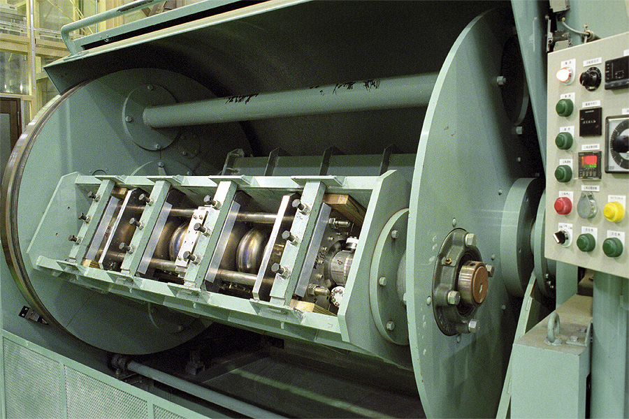 |
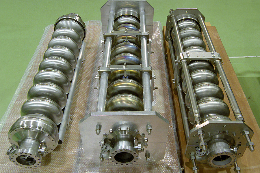
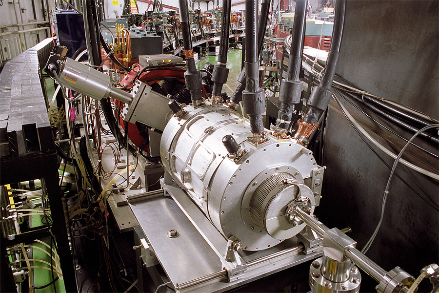
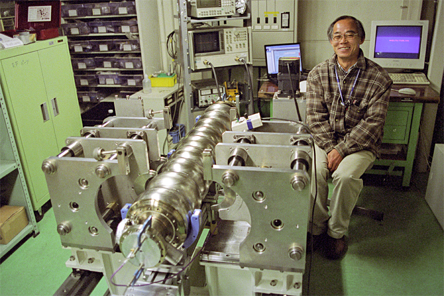
An L-band 9-cell cavity which was placed in a barrel-polishing setup. (Courtesy of KEK) |
||
 |
A TESLA-style 9-cell cavity built by a KEK group installed under GRP of an STF cryomodule. 2K Liq-He line has been installed now. (Courtesy KEK) |
||
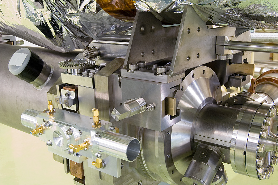 |
A TESLA-style 9-cell cavity built by a KEK group installed under GRP of an STF cryomodule. (Courtesy KEK) |
||
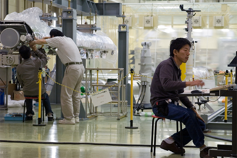 |
Survey crew recording the alignment of a 9-cell cavity after installation underneath GRP. (Courtesy KEK) |
||
 |
Crew determines the position of support ribs of a 9-cell cavity relative to the bracket off GRP. (Courtesy KEK) |
||
 |
The tuner being assembled on a TESLA-style basline 9-cell cavity at KEK. (Courtesy KEK) |
||
 |
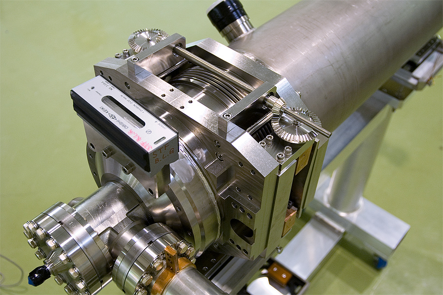
A TESLA-style baseline 9-cell cavity almost ready for pumping down. (Courtesy KEK) |
||
 |
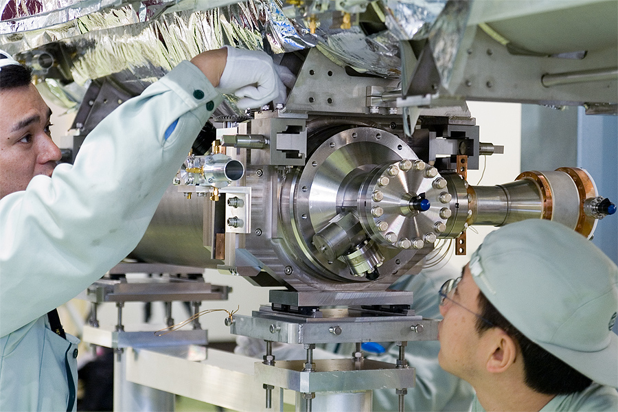
End view of a subasembly to go within the STF cryomodule. (Courtesy KEK) |
||
 |
Assembly work of the STF cryomodule. (Courtesy KEK) |
||
 |
TESLA 9-cell 1.3 GHz SRF cavities from ACCEL Corp. in Germany for ILC. (Courtesy Fermilab Visual Media Services) |
||
 |
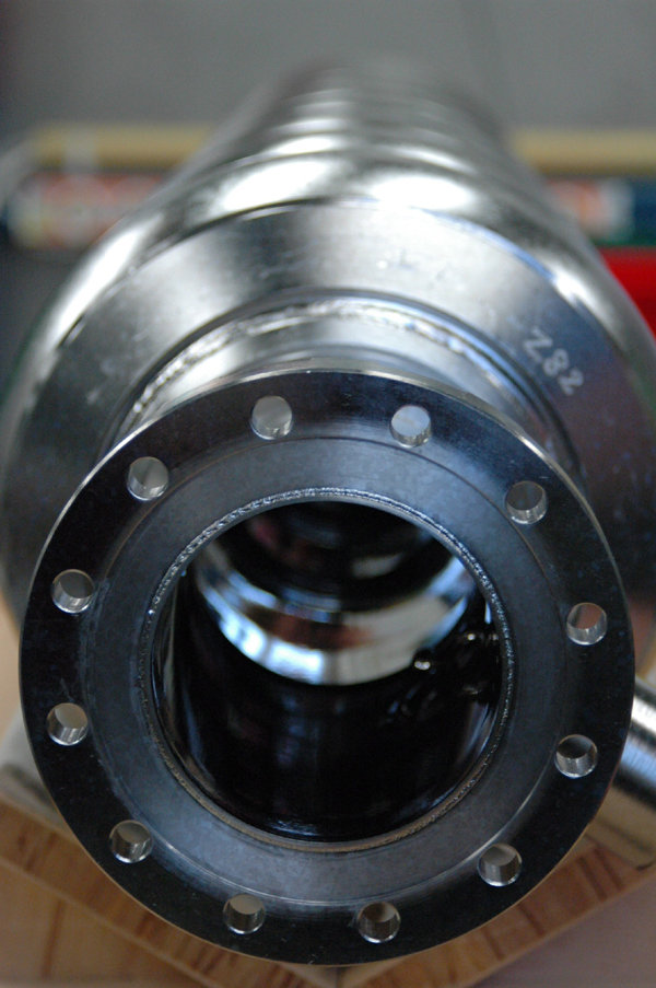
International Linear Collider ( ILC ) cryostat at MP9. (Courtesy of Fermilab Visual Media Services) |
||
 |
International Linear Collider ( ILC ) cryostat at MP9 - Jeff Elliott. (Courtesy of Fermilab Visual Media Services) |
||
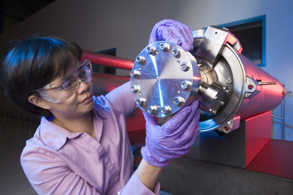 |
International Linear Collider ( ILC ) 1.3 GHz Type I cavity at MP9 - Mayling Wong. (Courtesy of Fermilab Visual Media Services) |
||
 |
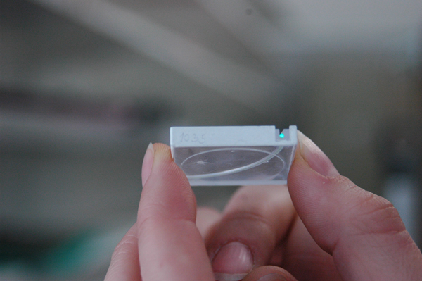
Half-cups for an L-band cavity. They are made of large-grain Nb sheets from Ning-Xia, delivered to KEK via IHEP, Beijing. (Courtesy of KEK) |
||
 |
Half-cups for an L-band cavity. They are made of large-grain Nb sheets from Brazil, delivered to KEK via Jefferson Lab, USA. (Courtesy of KEK) |
||
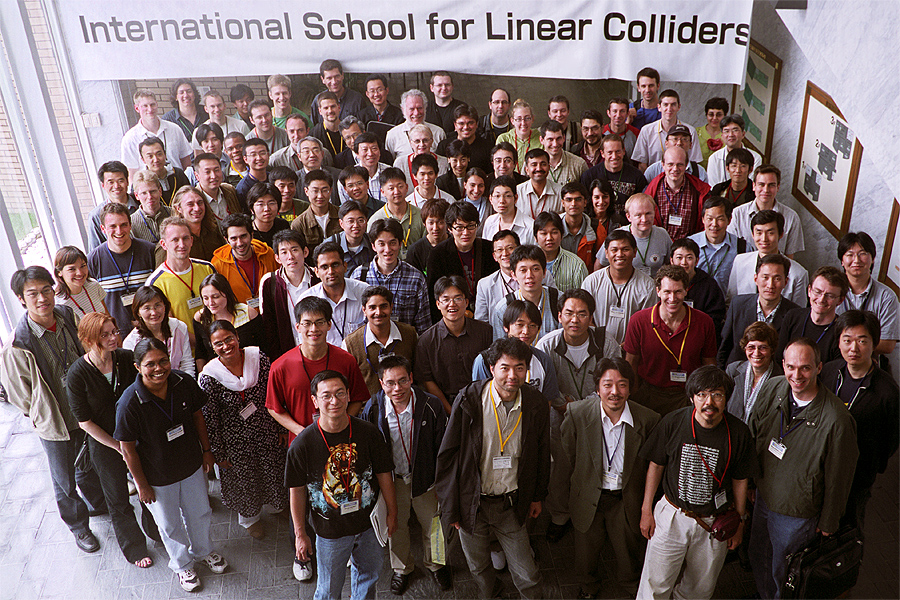 |
Participants at the International Acc School for Linear Colliders(Courtesy of KEK) |
||
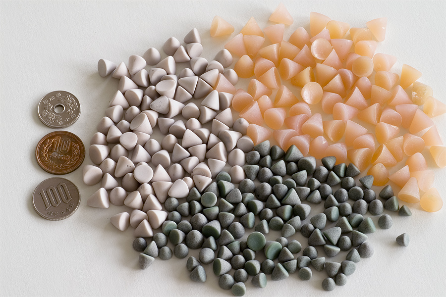 |
Grinding chips for centrifugal barrel polishing of cavity inner surfaces. (Courtesy of KEK) |
||
 |
International Linear Collider (ILC ) Test Area at MP9. (Credit Fermilab Visual Media Services) |
||
 |
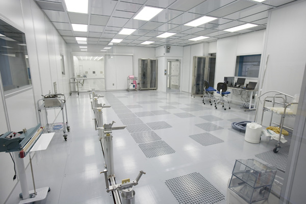
International Linear Collider (ILC) Cavity Prep Area at IB3. (Credit Fermilab Visual Media Services) |
||
 |
International Linear Collider (ILC) Test Area at MP9. (Credit Fermilab Visual Media Services) |
||
 |
International Linear Collider (ILC) Test Area at Meson. (Credit Fermilab Visual Media Services) |
||
 |
International Linear Collider (ILC) Test Area at Meson. (Credit Fermilab Visual Media Services) |
||
 |
Single-cell (ICHIRO design) cavities in stock. They are THE single-cell cavities who recorded the accelerating gradient in excess of ~50MV/m (See T.Saeki's presentation at KEK LCPAC, March, 2006 for additional information). They are continually used for refining the surface treatment procedure in the so-called "tight-loop" experiments, where high gradient tests are repeated, interlaced with BP, CP, EP and HPWR processing. (Courtesy of KEK) |
||
 |
Driver circuit and stripline kicker for testing the concept of ultra-fast kickers for use at ILC damping rings. This photo shows a driver circuit which has been assembled by LLNL group. Other circuits have been assembled by groups from KEK and DESY also. (Courtesy of KEK) |
||
 |
Laser-wire Beam Profile Monitor in the ATF Extraction Line. (Courtesy of KEK) |
||
 |
A batch of quadrupole magnets built for ATF2 by collaborators at IHEP, Beijing. (Courtesy of KEK) |
||
 |
Three units of L-band 9-cell cavities (TESLA-style design) built in 2005-2006. (Courtesy of KEK) |
||
 |
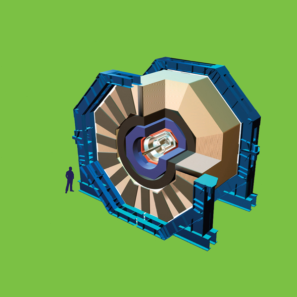
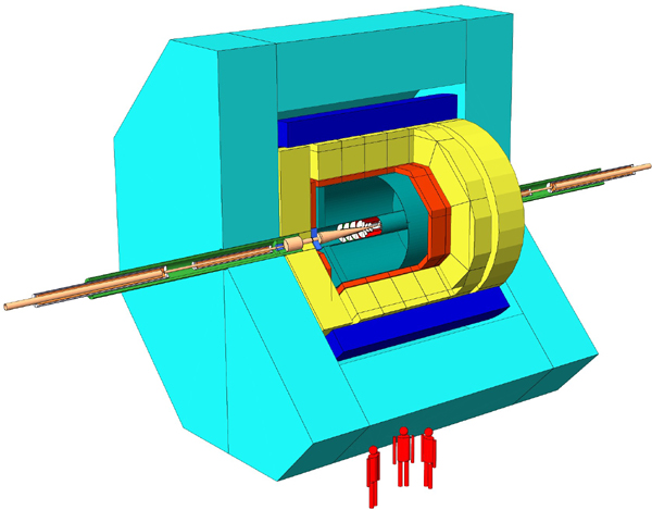
With calibration of the first half of the barrel Hadron Calorimeter (HB+) complete (using a radioactive source), preparations begin for its insertion into the solenoid for the Magnet Test and Cosmic Challenge (MTCC). It was moved out of its alcove at the beginning of March - a non-trivial (but completely successful) operation due to the proximity of one of the barrel yoke rings (YB+1). The other half of the barrel Hadron Calorimeter (HB-) and one of the endcaps (HE+) should also be calibrated before the MTCC. (Courtesy of Dave Barney, CERN) |
||
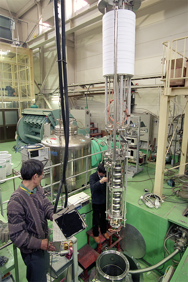 |
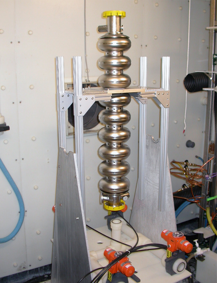
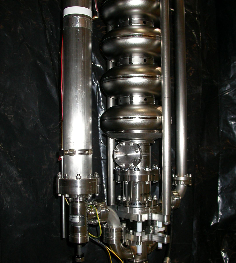
A 9-cell cavity being installed for vertical testing. (Courtesy of KEK) |
||
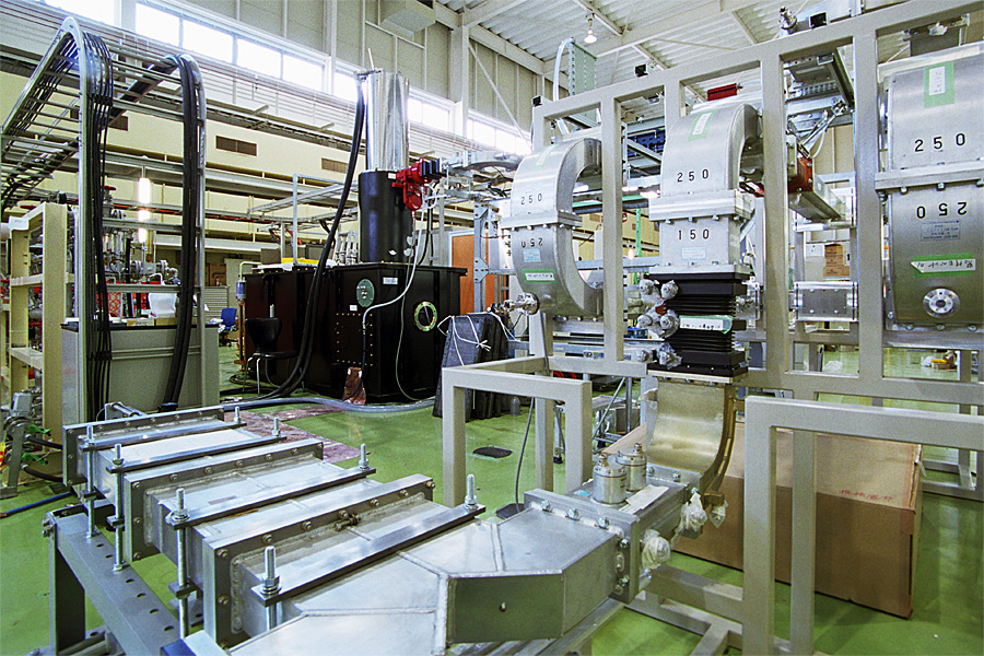 |
An L-band 5MW klystron and the RF waveguide system intalled at STF. (Courtesy of KEK) |
||
 |
Barry Barish, Director of ILC on tour of ILC R&D areas at Fermilab. (Courtesy of Fermilab Visual Media Services) |
||
 |
Barry Barish, Director of ILC on tour of ILC R&D areas at Fermilab. (Courtesy of Fermilab Visual Media Services) |
||
 |
Barry Barish, Director of ILC on tour of ILC R&D areas at Fermilab. (Courtesy of Fermilab Visual Media Services) |
||
 |
The Machine Advisory Committee for the ILC at a meeting at Daresbury Laboratory, UK, in January 2007. (Copyright 2007 GDE) |
||
 |
Simulation of a Higgs event in a future ILC detector (3-D view). (Copyright 2006 DESY) |
||
 |
Simulation of a Higgs event in a future ILC detector (side view). (Copyright 2006 DESY) |
||
 |
Artist's impression of one of the four detector concepts for the International Linear Collider, the 'Large Detector Concept' or LDC. (Copyright 2006 DESY) |
||
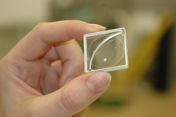 |
A prototype of a possible hadronic calorimeter for an ILC detector. A wavelength shifting fibre converts UV light into green light, a silicon photomultiplier then reads this light. (Copyright 2006 DESY) |
||
 |
A prototype of a possible hadronic calorimeter for an ILC detector. A wavelength shifting fibre converts UV light into green light, a silicon photomultiplier then reads this light. (Copyright 2006 DESY) |
||
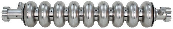 |
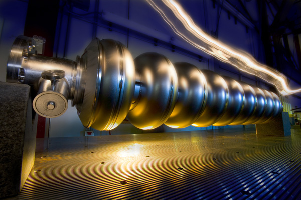
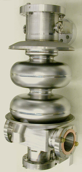
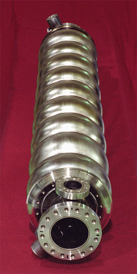
A superconducting TESLA cavity. (Copyright 2006 DESY) |
||
 |
Simulation of a Higgs event in a future ILC detector (front view). (Copyright 2006 DESY) |
||
 |
A superconducting niobium cavity (Copyright 2006 DESY) |
||
 |
A superconducting niobium cavity (Copyright 2006 DESY) |
||
 |
A superconducting niobium cavity (Copyright 2006 DESY) |
||
 |
A prototype of a possible hadronic calorimeter for an ILC detector (array of scintillators with mounted photodetectors) (Copyright 2006 DESY) |
||
 |
Fumio Furuta, KEK, and Hyong Suk KIM, Kyungpook National University, prepares a 9-cell ICHIRO cavity for high gradient field test in the clean room of STF, KEK. (Credit KEK) |
||
 |
Fumio Furuta, KEK, and Hyong Suk KIM, Kyungpook National University, prepares a 9-cell ICHIRO cavity for high gradient field test in the clean room of STF, KEK. (Credit KEK) |
||
 |
The logo of the International Linear Collider. (Courtesy of ILC GDE) |
||
 |
The logo of the International Linear Collider. (Courtesy of ILC GDE) |
||
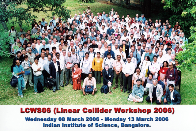 |
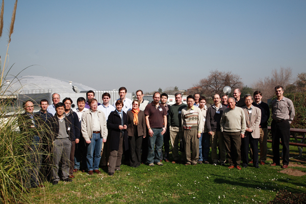
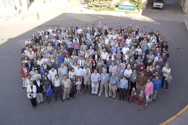
Group Photo from Linear Collider Workshop 2006 in Bangalore, India. (Courtesy of ILC GDE) |
||
 |
Sending high-density packets of positrons through a beam pipe produces electron clouds that diffuse the positron beam. (Credit: Symmetry magazine/Sandbox Studio) |
||
 |
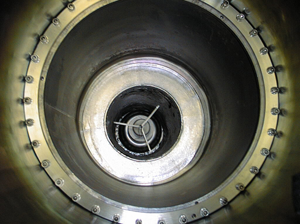
This is how the electrons and positrons would see, as they are accelerated in the ILC main linacs, if they had eyes. Inside view of a 9-cell cavity. (Courtesy of KEK) |
||
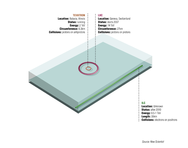 |
Dimensions of Fermilab's Tevatron, currently the world's most powerful particle accelerator; the Large Hadron Collider, soon to begin operating in Europe; and the proposed International Linear Collider. (Courtesy of Sandbox Studio) |
||
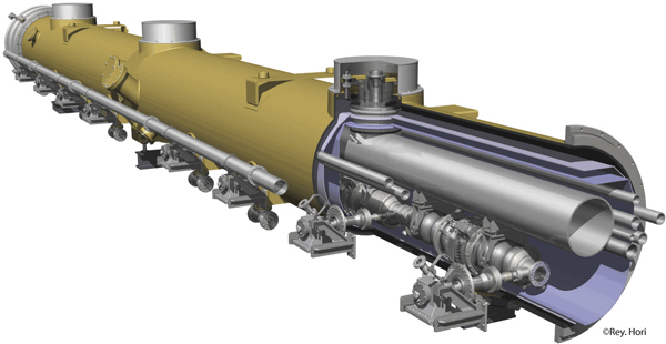 |
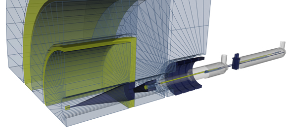
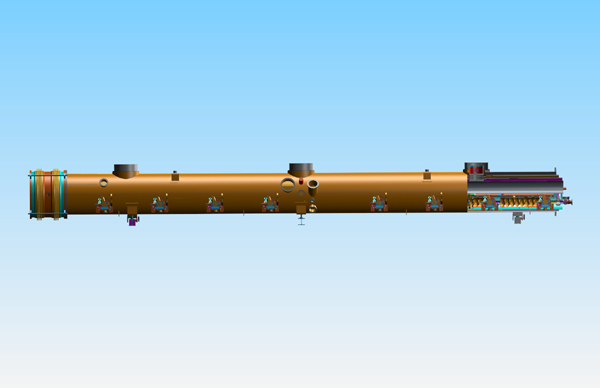
3-D rendition of a cryomodule for ILC. (Courtesy of KEK) |
||
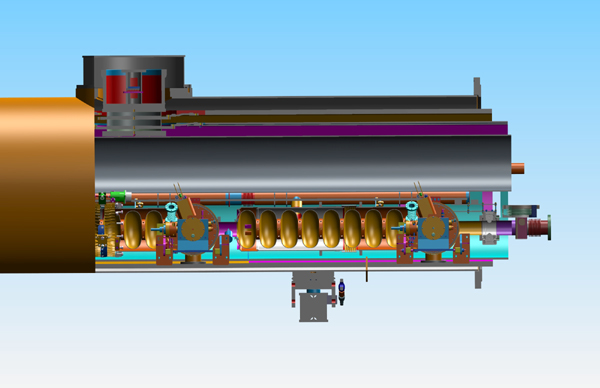 |
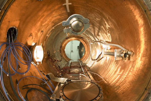
An inside view of a cryomodule for the ILC. (Courtesy of Fermilab) |
||
 |
An inside view of a cryomodule for the ILC. (Courtesy of Fermilab) |
||
 |
2 Cell Cornell ERL Injector Cavity. (Courtesy Cornell - LEPP Laboratory) |
||
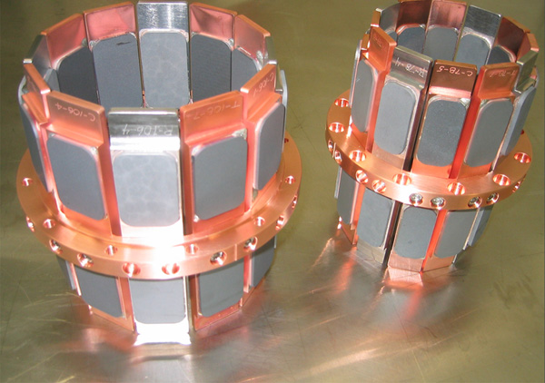 |
Cornell ERL absorder rings. (Courtesy Cornell-LEPP Laboratory) |
||
 |
Cornell cavity test pit. (Courtesy Cornell-LEPP Laboratory) |
||
 |
RF cavities. (Courtesy Cornell - LEPP Laboratory) |
||
 |
BCP of ILC Cornell cavity. (Courtesy Cornell - LEPP) |
||
 |
Cebat 5-cell cavity. (Courtesy Cornell - LEPP) |
||
 |
CESR SRF cryostat. (Courtesy Cornell - LEPP) |
||
 |
Cornell ERL hom load. (Courtesy Cornell - LEPP) |
||
 |
Cornell ERL inject input coupler. (Courtesy Cornell - LEPP) |
||
 |
Cornell SRF cavity test pit. (Courtesy Cornell - LEPP) |
||
 |
Cornell vert cavity test. (Courtesy Cornell - LEPP) |
||
 |
EB welding Cornell ERJ injector cavity. (Courtesy Cornell - LEPP) |
||
 |
High temperature cavity vac furnace. (Courtesy Cornell - LEPP) |
||
 |
ILC cavity test set up Cornell. (Courtesy Cornell - LEPP) |
||
 |
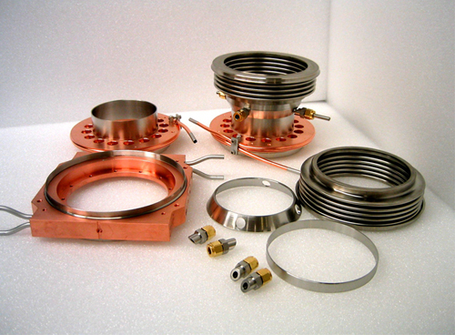
Parts Cornell ERL injector SRF cavities. (Courtesy Cornell - LEPP) |
||
 |
Cornell cavity test pit. (Courtesy Cornell - LEPP) |
||
 |
Cornell ERL hom absorber. (Courtesy Cornell - LEPP) |
||
 |
New extraction kicker for the ATF Damping Ring. (Courtesy of KEK) |
||
 |
Arc section of the ATF Damping Ring. (Courtesy of KEK) |
||
 |
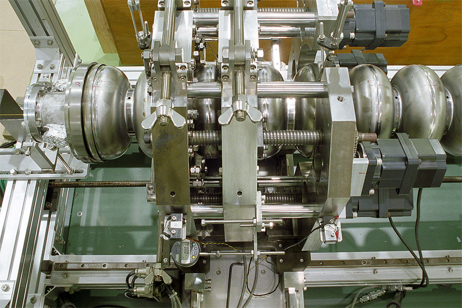
An L-band 9-cell cavity which was placed in the pretuning setup. (Courtesy of KEK) |
||
 |
An L-band 9-cell cavity which was placed in the pretuning setup. (Courtesy of KEK) |
||
 |
An L-band 9-cell cavity which was placed in the pretuning setup. (Courtesy of KEK) |
||
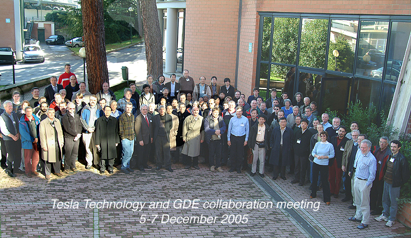 |
TESLA Technology and GDE Collaboration at Frascati, 2005. (Credit INFN Frascati) |
||
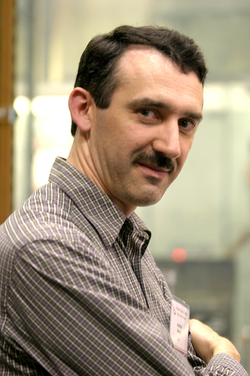 |
ILC Global Design Effort member Andrei Seryi. (Courtesy of Fermilab Visual Media Services) |
||
 |
ILC Global Design Effort member Masao Kuriki. (Courtesy of KEK) |
||
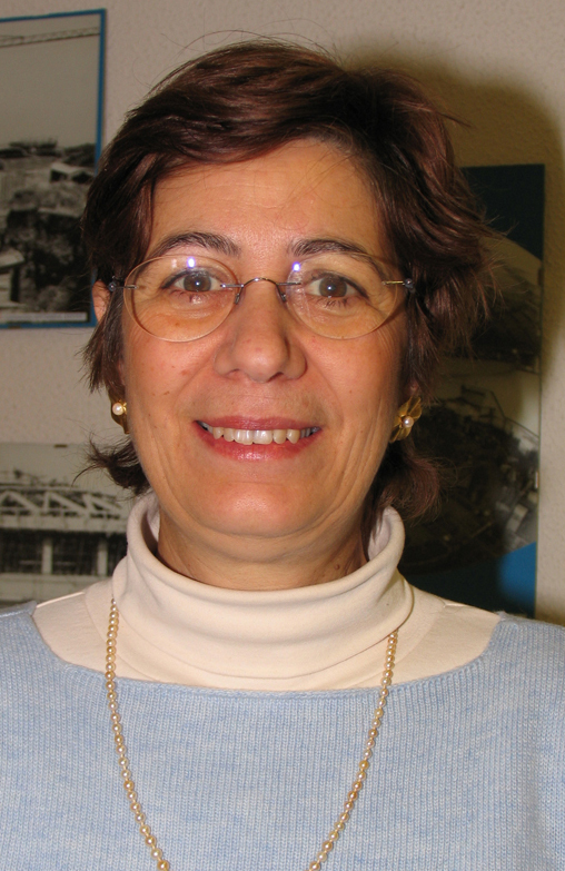 |
ILC Global Design Effort member Susanna Guiducci. (Courtesy of Fermilab Visual Media Services) |
||
 |
ILC Global Design Effort member Marc Ross. (Courtesy of Fermilab Visual Media Services) |
||
 |
ILC Global Design Effort member Kiyoshi Kubo. (Courtesy of KEK) |
||
 |
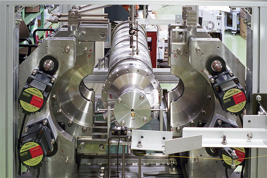
An L-band 9-cell cavity which was placed in a barrel-polishing setup (Courtesy of KEK) |
||
 |
A staff member and an L-band 9-cell cavity (LL-"Ichiro"-cavity) which was placed in a pre-tuning setup. (Courtesy of KEK) |
||
 |
TESLA 9-cell 1.3 GHz SRF cavities from ACCEL Corp. in Germany for ILC. (Courtesy Fermilab Visual Media Services) |
||
 |
Press molds for fabricating half cavities. (Courtesy of KEK) |
||
 |
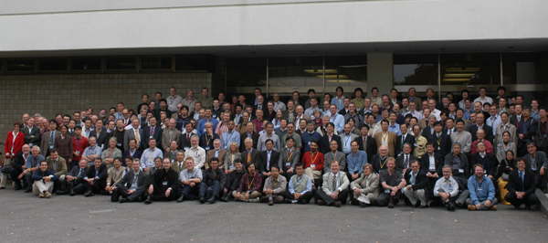
2005 ILC Snowmass Conference Participants in Snowmass, CO. (Courtesy of Fermilab Visual Media Services) |
||
 |
ILC Global Design Effort member Gerald Dugan.(Courtesy of Fermilab Visual Media Services) |
||
 |
DESY Director at the Snowmass Conference 2005. (Courtesy of Fermilab Visual Media Services) |
||
 |
2005 ILC Snowmass Workshop - Talk given by CERN Director General Robert Aymar. (Courtesy of Fermilab Visual Media Services) |
||
 |
ILC Global Design Effort member Karsten Buesser.(Courtesy of Fermilab Visual Media Services) |
||
 |
ILC Global Design Effort member Carlo Pagani. (Courtesy of Fermilab Visual Media Services) |
||
 |
GDE Communicators at ILC Snowmass 2005 Conference - Public Participation Workshop (Courtesy of Fermilab Visual Media Services) |
||
 |
Shin-ichi Kurokawa at the Snowmass 2005 Conference. (Courtesy of Fermilab Visual Media Services) |
||
 |
ILC Global Design Effort member Vic Kuchler. (Courtesy of Fermilab Visual Media Services) |
||
 |
ILC Global Design Effort member Maxine Hronek. (Courtesy of Fermilab Visual Media Services) |
||
 |
Pier Oddone, Robin Staffin, Fred Gilman at the Snowmass Conference 2005. (Courtesy of Fermilab Visual Media Services) |
||
 |
ILC Global Design Effort member Youhei Morita. (Courtesy of Fermilab Visual Media Services) |
||
 |
Neil Calder at ILC Snowmass 2005 Conference - Public Participation Workshop . (Courtesy of Fermilab Visual Media Services) |
||
 |
ILC Global Design Effort member Robert Kephart. (Courtesy of Fermilab Visual Media Services) |
||
 |
ILC Global Design Effort member Shekhar Mishra. (Courtesy of Fermilab Visual Media Services) |
||
 |
ILC Global Design Effort member Elizabeth Clements. (Courtesy of Fermilab Visual Media Services) |
||
 |
ILC Global Design Effort member Jim Brau. (Courtesy of Fermilab Visual Media Services) |
||
 |
ILC Global Design Effort member Wilhelm Bialowons. (Courtesy of Fermilab Visual Media Services) |
||
 |
ILC Global Design Effort member Andy Wolski.(Courtesy of Fermilab Visual Media Services) |
||
 |
ILC Global Design Effort member Chris Adophson. (Courtesy of Fermilab Visual Media Services) |
||
 |
ILC Global Design Effort member Francois Richard. (Courtesy of Fermilab Visual Media Services) |
||
 |
ILC Global Design Effort member Lutz Lilje. (Courtesy of Fermilab Visual Media Services) |
||
 |
ILC Global Design Effort member Nick Walker. (Courtesy of Fermilab Visual Media Services) |
||
 |
ILC Global Design Effort member Daniel Schulte. (Courtesy of Fermilab Visual Media Services) |
||
 |
ILC Global Design Effort member Jean-Pierre Delahaye. (Courtesy of Fermilab Visual Media Services) |
||
 |
ILC Global Design Effort member Olivier Napoly.(Courtesy of Fermilab Visual Media Services) |
||
 |
ILC Global Design Effort member Grahame Blair.(Courtesy of Fermilab Visual Media Services) |
||
 |
ILC Global Design Effort member Tom Markiewicz.(Courtesy of Fermilab Visual Media Services) |
||
 |
ILC Global Design Effort member Philip Bambade. (Courtesy of Fermilab Visual Media Services) |
||
 |
ILC Global Design Effort member Terry Garvey.(Courtesy of Fermilab Visual Media Services) |
||
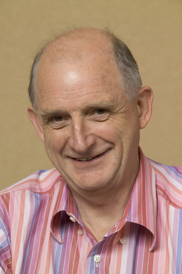 |
ILC Global Design Effort member David Miller. (Courtesy of Fermilab Visual Media Services) |
||
 |
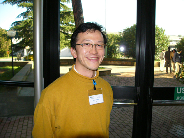
ILC Global Design Effort member Nobu Toge. Courtesy of Fermilab Visual Media Services) |
||
 |
ILC Global Design Effort member Kaoru Yokoya.(Courtesy of Fermilab Visual Media Services) |
||
 |
ILC Global Design Effort member Fumihiko Takasaki.(Courtesy of Fermilab Visual Media Services) |
||
 |
ILC Global Design Effort member Sasha Srinsky.(Courtesy of Fermilab Visual Media Services) |
||
 |
ILC Global Design Effort member Kenji Saito.(Courtesy of Fermilab Visual Media Services) |
||
 |
ILC Global Design Effort member Atsushi Enomoto.(Courtesy of Fermilab Visual Media Services) |
||
 |
ILC Global Design Effort member Hitoshi Yamamoto.(Courtesy of Fermilab Visual Media Services) |
||
 |
ILC Global Design Effort member Warren Funk. (Courtesy of Fermilab Visual Media Services) |
||
 |
ILC Global Design Effort member Ewan Paterson.(Courtesy of Fermilab Visual Media Services) |
||
 |
ILC Global Design Effort member Eun San Kim. (Courtesy of Fermilab Visual Media Services) |
||
 |
ILC Global Design Effort member Dieter Proch.(Courtesy of Fermilab Visual Media Services) |
||
 |
ILC Global Design Effort member Tom Himel. (Courtesy of Fermilab Visual Media Services) |
||
 |
ILC Global Design Effort member Shane Koscielniak.(Courtesy of Fermilab Visual Media Services) |
||
 |
ILC Global Design Effort member Hitoshi Hayano.(Courtesy of Fermilab Visual Media Services) |
||
 |
ILC Global Design Effort member Jie Gao. (Courtesy of Fermilab Visual Media Services) |
||
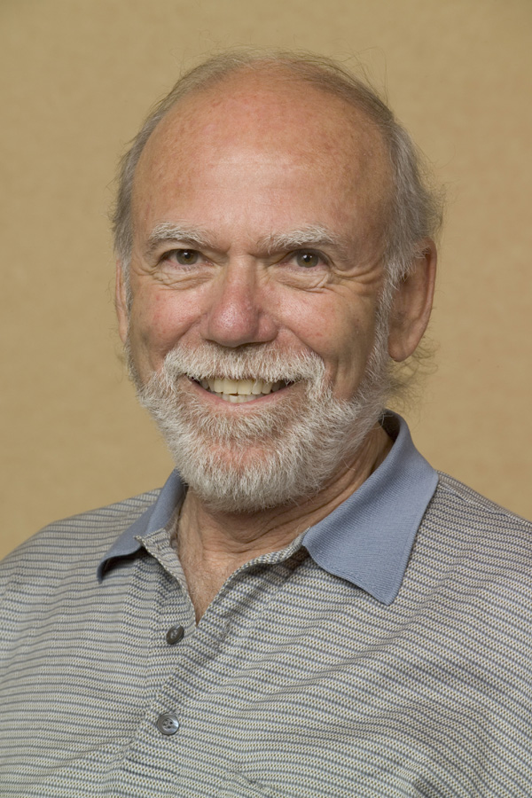 |
ILC Global Design Effort member Barry Barish. (Courtesy of Fermilab Visual Media Services) |
||
 |
ILC Global Design Effort member Hyoung Suk Kim. (Courtesy of Fermilab Visual Media Services) |
||
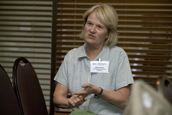 |
Judy Jackson at ILC Snowmass 2005 Conference - Public Participation Workshop. (Courtesy of Fermilab Visual Media Services) |
||
 |
SLAC Director Jonathan Dorfan at the Snowmass conference 2005. (Courtesy of Fermilab Visual Media Services) |
||
 |
SLAC Director Jonathan Dorfan and DESY Director Albrecht Wagner at the Snowmass conference 2005. (Courtesy of Fermilab Visual Media Services) |
||
 |
L-band 5MW klystron under testing at KEK. (Courtesy of KEK) |
||
 |
2nd model of KEK L-band low-loss 9-cell cavity (ICHIRO cavity). (Courtesy of KEK) |
||
 |
TESLA 9-cell 1.3 GHz SRF cavities from ACCEL Corp. in Germany for ILC. (Courtesy Fermilab Visual Media Services) |
||
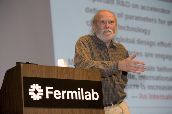 |
Annual Users' Meeting Speaker Barry Barish of Caltech. (Courtesy Fermilab Visual Media Services) |
||
 |
1st model of KEK =labnd low-loww 9-cell cavity (ICHIRO cavity). (Courtesy of KEK) |
||
 |
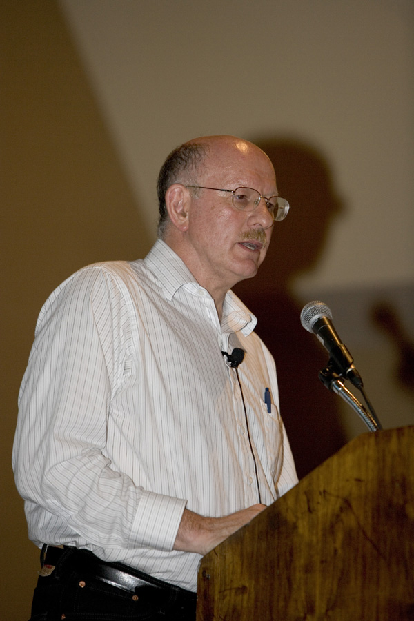
Professor Barry Barish, Director of the Global Design Effort for the proposed International Linear Collider. (Courtesy of SLAC) |
||
 |
Professor Barry Barish, Director of the Global Design Effort for the proposed International Linear Collider. (Courtesy of SLAC) |
||
 |
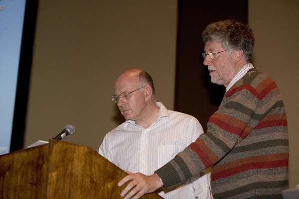
SLAC Director, Jonathan Dorfan, and Barry Barish, Director of the Global Design Effort for the proposed International Linear Collider. (Courtesy of SLAC) |
||
 |
Artist impression of the International Linear Collider. (Courtesy of SLAC) |
||
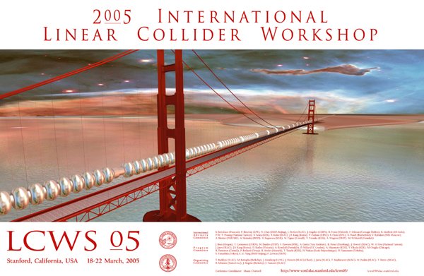 |
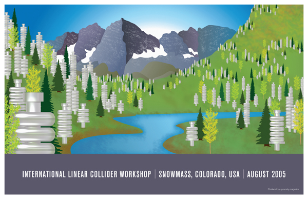
Poster for International Linear Collider workshop 2005. (Credit SLAC) |
||
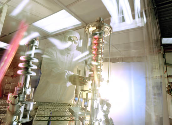 |
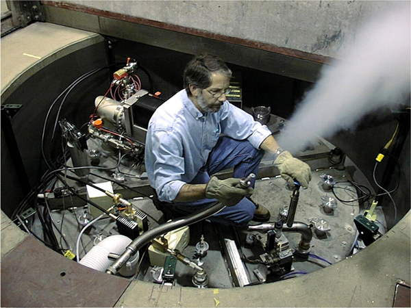
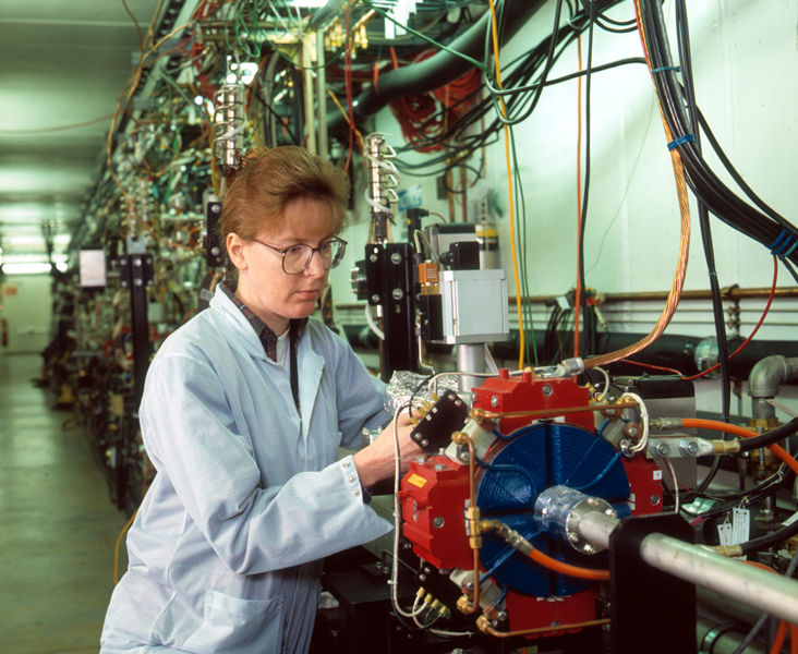
"Cold" RF Cavities. Scientist James Santucci assembles a superconducting RF structure in a clean room at Fermilab.(Courtesy of Peter Ginter) |
||
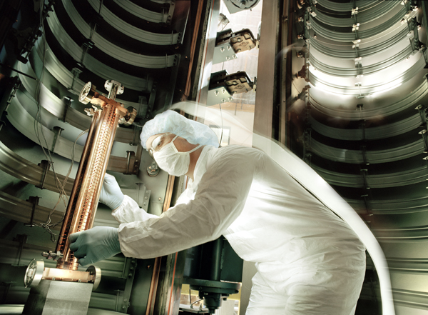 |
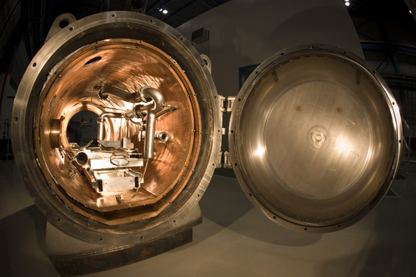
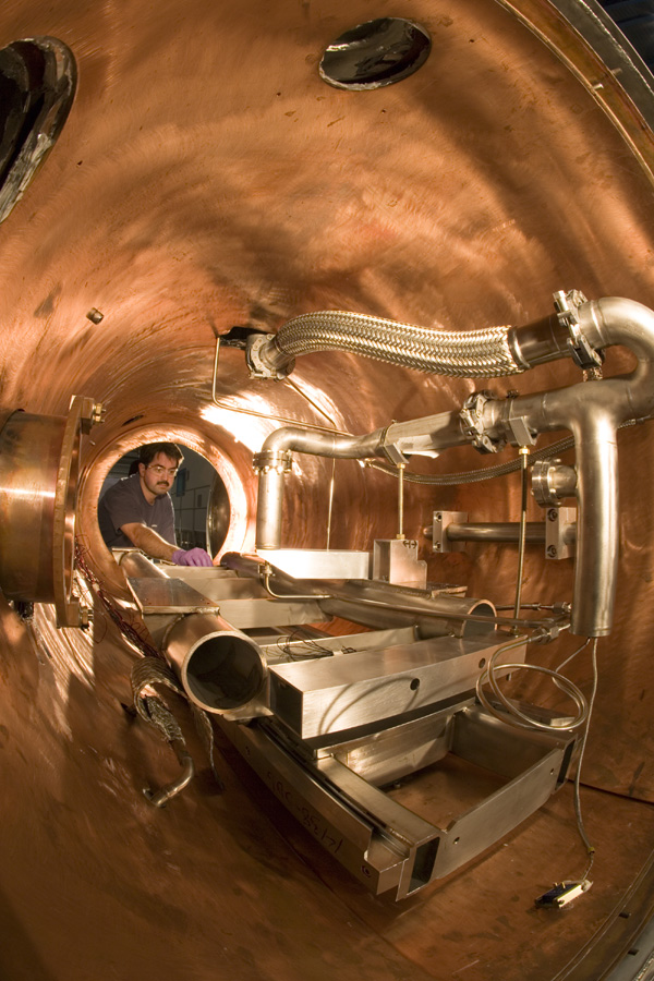
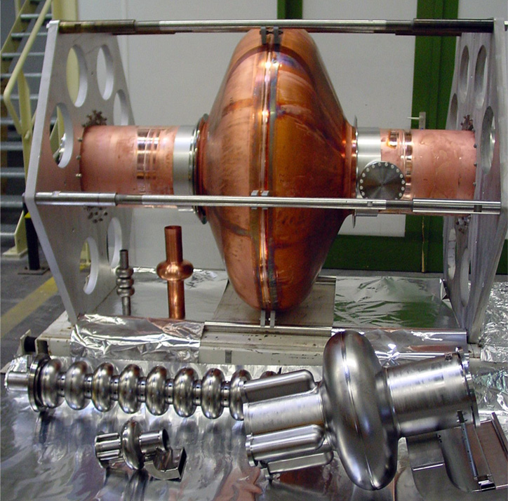
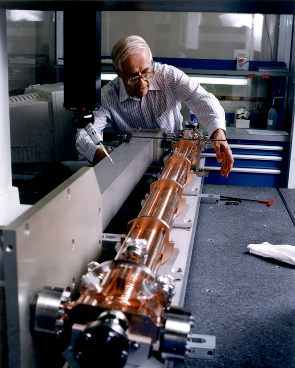
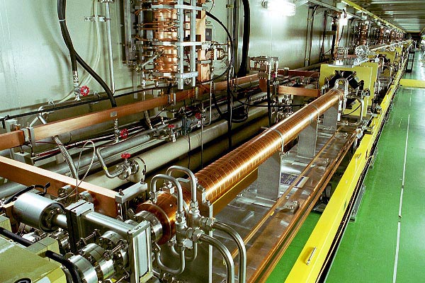
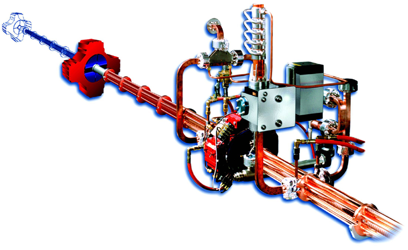
A prototype accelerating structure for a linear collider made of copper. This “warm” accelerator technology was not selected for the design of the proposed International Linear Collider. (Credit Peter Ginter) |
||
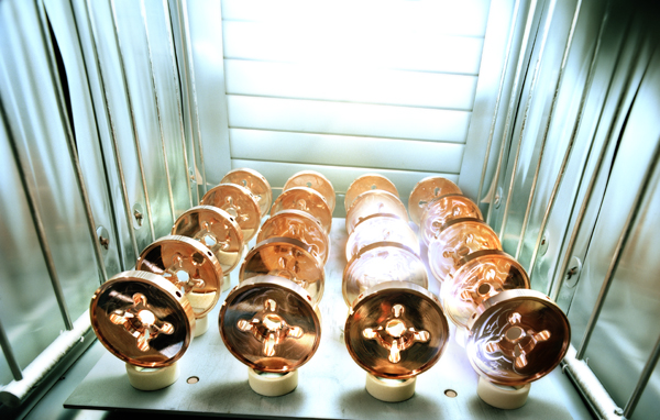 |
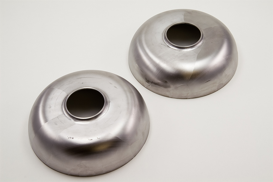
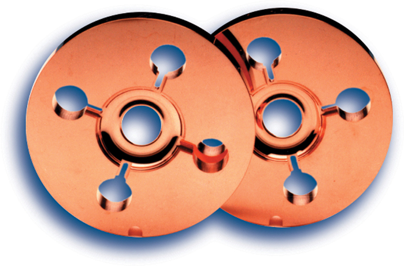
Precisely machined copper disks, components of a room-temperature radiofrequency accelerating structure. This “warm” technology was not selected for the design of the proposed International Linear Collider. (Credit Peter Ginter) |
||
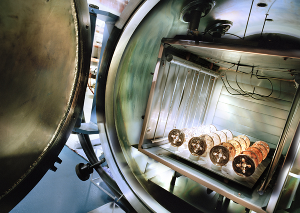 |
Precisely machined copper disks, components of a room-temperature radiofrequency accelerating structure. This technology was not selected for the design of the proposed International Linear Collider. (Credit Peter Ginter) |
||
 |
ILC Global Design Effort member Perrine Royole-Degieux. (Courtesy of Fermilab Visual Media Services) |
||
 |
Poster for Snowmass Conference 2005. (Courtesy of Symmetry Magazine) |
||
 |
ILC Global Design Effor member Tetsuo Shidara. (Courtesy of KEK) |
||
 |
A group photo of the ILC workshop at KEK, November 2004. (Courtesy of KEK) |
||
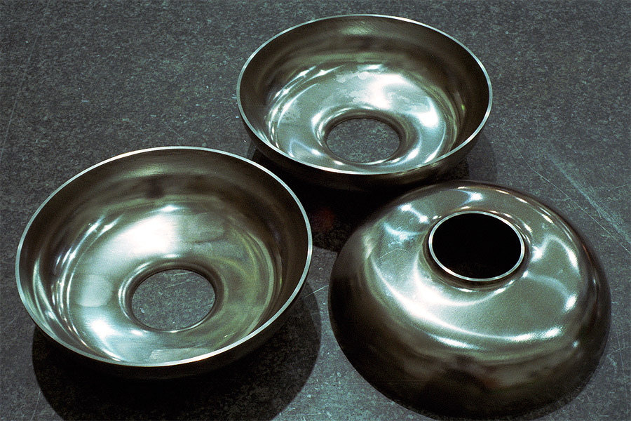 |
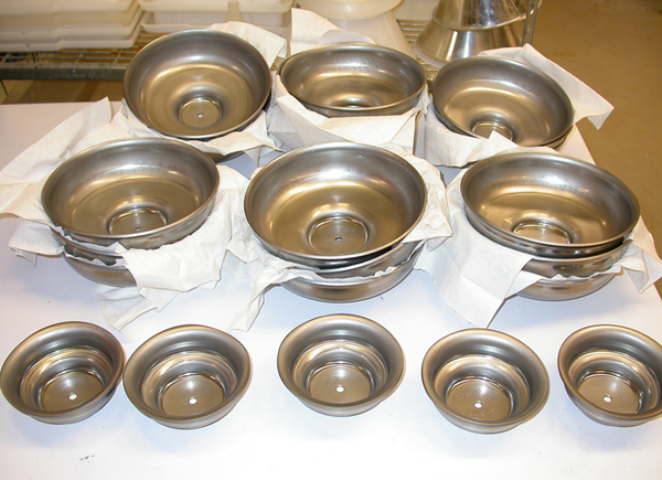
Half cavities after press molding and trimming. (Courtesy of KEK) |
||
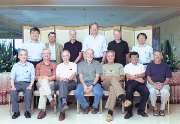 |
International Technology Recommendation Panel. Front row, left to right: Akira Masaike, George Kalmus, Volker Soergel, Barry Barish, Giorgio Bellettini, Hirotaka Sugawara,Paul Grannis Back row: Gyung-Su Lee, Jean-Eude Augustin, David Plane (secretary), Jonathan Bagger, Norbert Holtkamp, Katsunobu Oide |
||
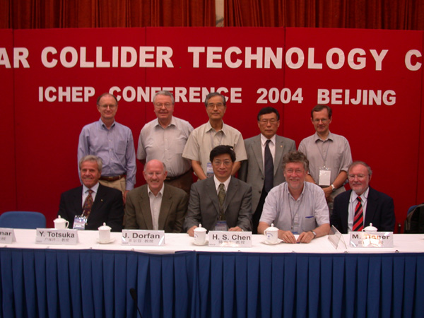 |
The International Committee for Future Accelerators (ICFA) at the ICHEP 2004 conference in Beijing. (Courtesy of SLAC) |
||
 |
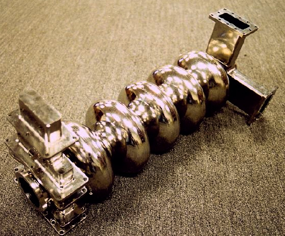
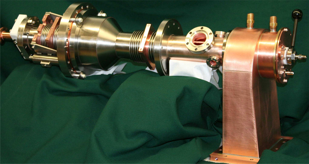
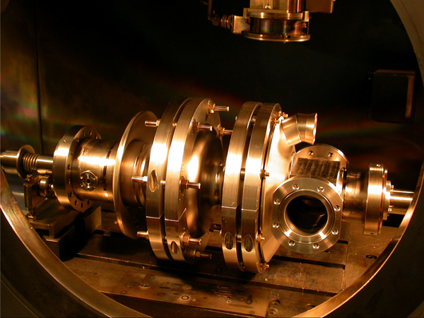
3rd Harmonic, 3.9 GHz Accelerating, 9 Cell Niobium Cavity.(Courtesy of Don Mitchell, Fermilab Technical Division) |
||
 |
3rd Harmonic, 3.9 GHz Accelerating, 9 Cell Niobium Cavity. .(Courtesy of Don Mitchell, Fermilab Technical Division) |
||
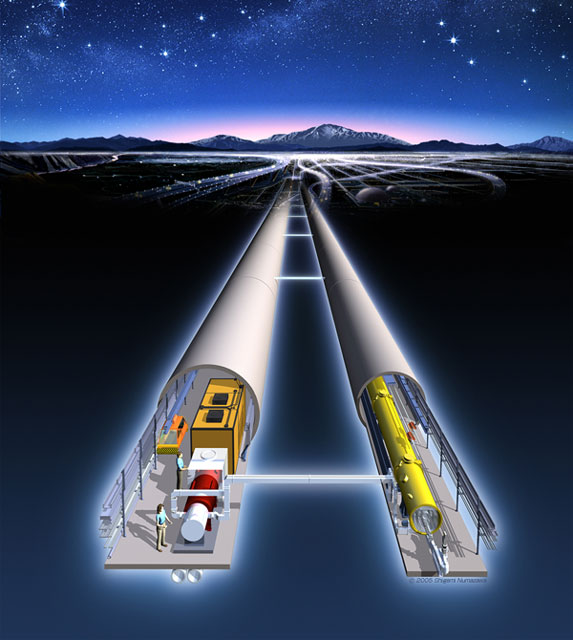 |
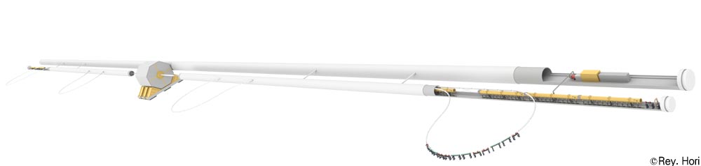
Artist's futuristic drawing of the international linear collider. Electron-positron linear accelerator with its main tunnel is accompanied with a smaller service tunnel for the klystron. Total length of the tunnels are expected to be about 40km. (Courtesy KEK) |
||
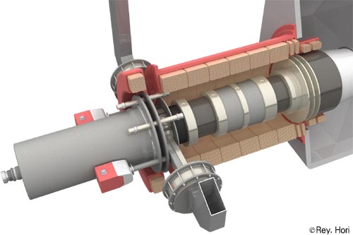 |
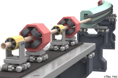
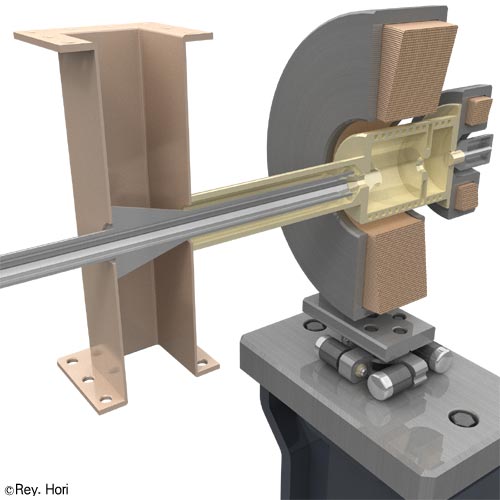
Artists's rendering of klystron for the international linear collider. (Courtesy of KEK) |
||
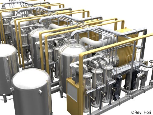 |
Artists's rendering of helium plant for the international linear collider. (Courtesy of KEK) |
||
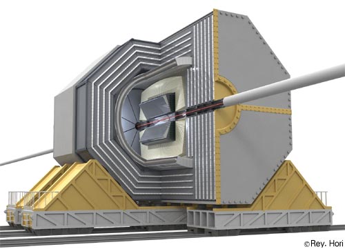 |
Artists's rendering of the planned collider detector for the international linear collider. (Courtesy of KEK) |
||
 |
Artists's rendering of a part of the damping ring for the international linear collider. (Courtesy of KEK) |
||
 |
Artists's rendering of cryomodule for the international linear collider. (Courtesy of KEK) |
||
 |
Artists's rendering of the electron source for the international linear collider. (Courtesy of KEK) |
||
 |
Artists's rendering of the international linear collider. (Courtesy of KEK) |
||
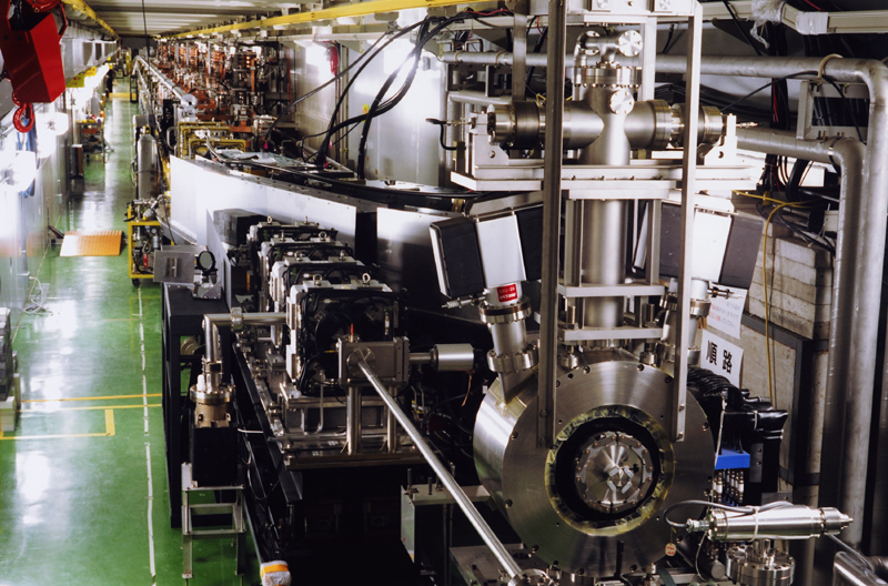 |
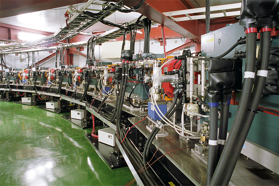
The ATF linear accelerator seen from downstream. After the electron beam is accelerated to 1.3 GeV, it is transported to the damping Ring through bending magnets. At the right side of this picture, you can see an apparatus for the experiment on positron production. (Courtesy of KEK) |
||
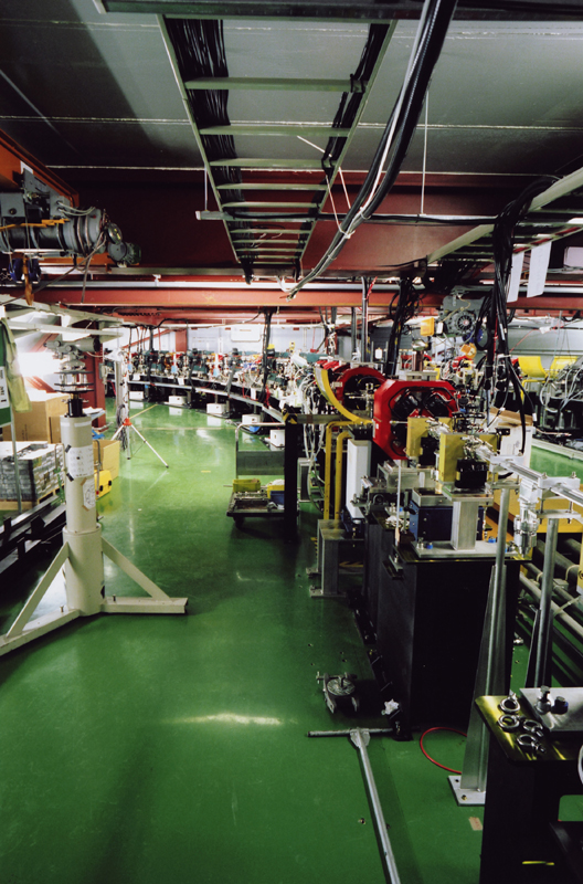 |
Accelerator Test Facility (ATF) is the forefront of the low-emittance and high intensity beam steering technology. These technologies are the essential part of the future linear collider experiment. Seen in the photo is the northwest part of the ATF Damping Ring, with the arc section of the ring and the beam extraction line in the background. (Courtesy of KEK) |
||
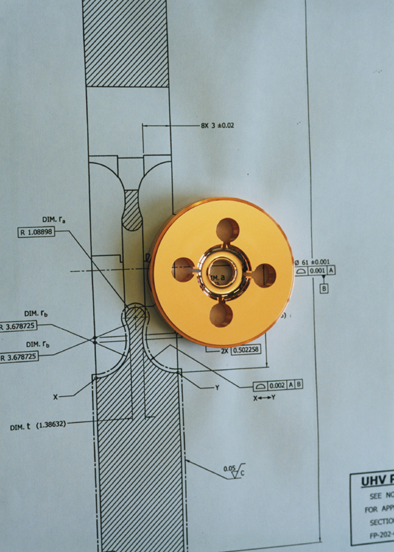 |
RDDS disk for X-band Linear Collider. Mechanical Engineering Center produces an 1 micron accuracy X-band radio frequency cavity for the future linear collider. (Courtesy of KEK) |
||
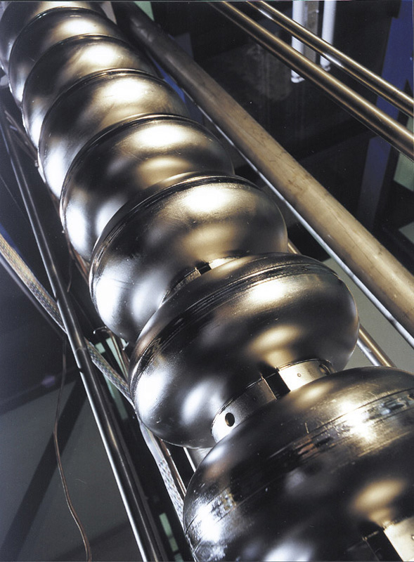 |
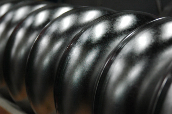
TESLA technology Superconducting accelerator structures of niobium, the so called resonators, are components of the future linear accelerator. (Source: DESY Hamburg) |
||
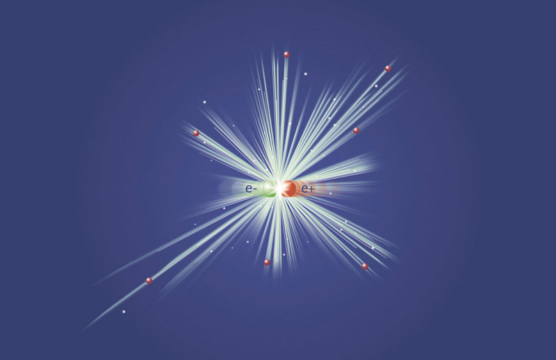 |
Matter meets antimatter. If an electron and a positron collide at at high speed in the TESLA accelerator, both are annihilated - i.e. they are converted into pure energy, out of which new elementary particles can arise. (Source: DESY Hamburg) |
||
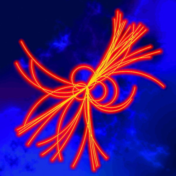 |
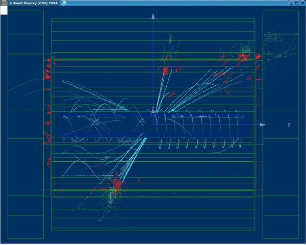
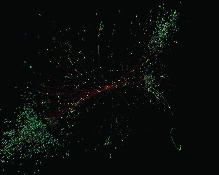
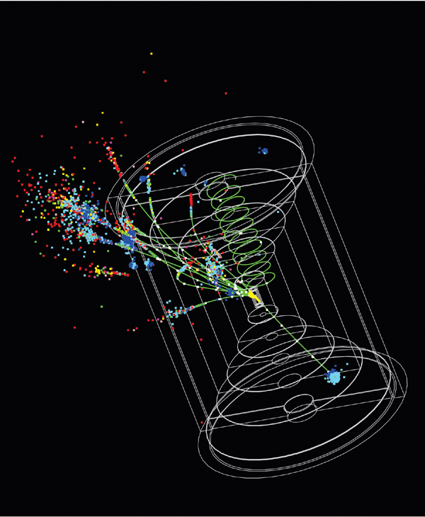
Particle tracks. Computer simulation of the decay of a Higgs particle. (Source: DESY Zeuthen) |
||
 |
Harry Hoag working on a component of the NLCTA.(Photo Courtesy of Stanford Linear Accelerator Center) |
||
 |
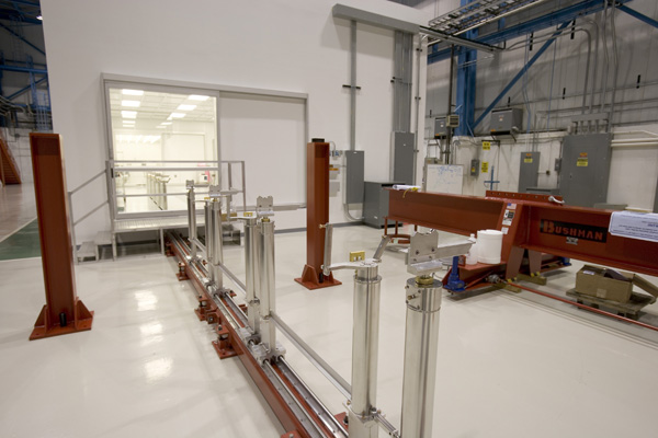
The Next Linear Collider Test Accelerator facility. (Photo Courtesy of Stanford Linear Accelerator Center) |
||
 |
The Next Linear Collider Test Accelerator facility. (Photo Courtesy of James E. Stoots) |
||
 |
Precision copper disks, components of accelerating structure for a proposed linear collider. (Photo Courtesy of Stanford Linear Accelerator Center) |
||
 |
Waveguides for linear collider under development at Accelerator Test Facility at KEK. (Courtesy of KEK) |
||
 |
Superconducting accelerator structures at the TESLA test facility at DESY in Hamburg. (Source: DESY Hamburg) |
||
 |
Simulated response of linear collider detector to supersymmetry displaying the characteristic signature of a lepton, a hadronic jet and missing transverse energy. (Credit: Norman Graf) |
||
 |
Simulated event illustrating the associated production of a Higgs particle and a Z boson at a linear collider. (Credit: Norman Graf) |
||
 |
Simulated response of linear collider detector to the production of two Z bosons. Each of the Z bosons decays into a pair of jets. (Credit: Norman Graf) |
||
 |
Prototype linear collider accelerating structures, under development at SLAC. (Credit: SLAC) |
||
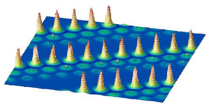 |
Nanospin. Calculated spin density of cobalt nanowires on platinum. Large peaks reflect the magnetization of Co sites; whereas the small peaks reflect that induced in the Pt substrate. (Courtesy: Brookhaven National Laboratory) |
||
 |
Artist impression of the NLC (Next Linear Collider). (Courtesy of SLAC and Nicolle Rager) |
||
 |
Artist impression of the NLC (Next Linear Collider). (Courtesy of SLAC and Nicolle Rager) |
||
 |
Electron Positron Linear Collider Project has been developed as a next principal project with consensus of Japanese high energy physicists, which is called as GLC however it has been known as JLC until March 2003. Center-of-mass energy shall be 500GeV at the first stage of linear collider. This project is expected to resolve numerous puzzles in world of elementary particles and cosmic creation. (Courtesy of KEK) |
||
 |
Neutralino: Simulation of the signature of a neutralino, a predicted supersymmetric particle that is one candidate for dark matter. (Credit: Norman Graf) |
||
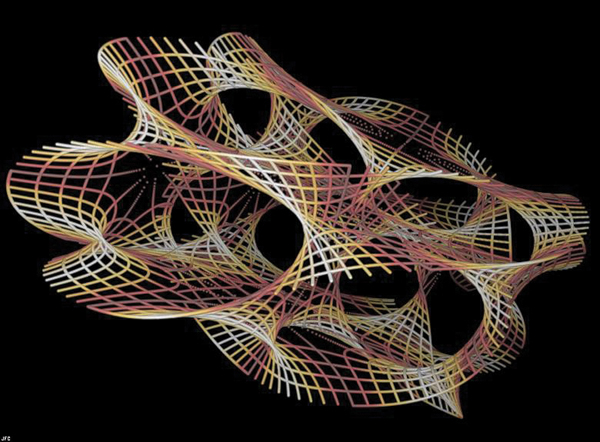 |
Superstrings: A computer's graphical representation of multi-dimensional spacetime. (Credit: Jean-Francois Colonna) |
||
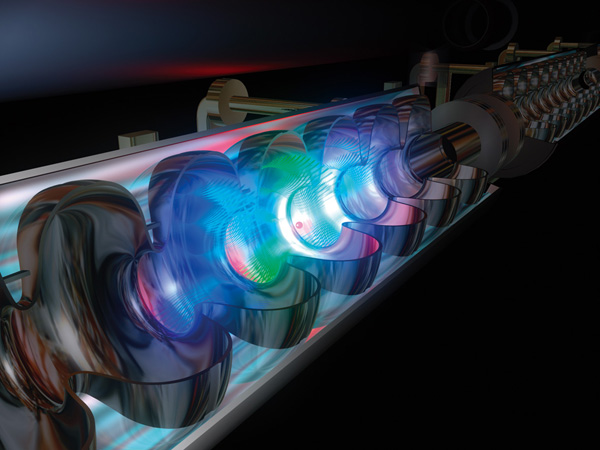 |
Computer animation of the field inside a superconducting accelerator resonator. In August 2004, the International Committee of Future Accelerators chose this technology---which has been developed and tested at the TESLA Test Facility at DESY---for the next particle physics project, the International Linear Collider (ILC). (Source: DESY Hamburg) |
||
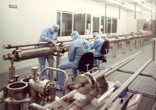 |
The superconducting structures for the TESLA Test Facility at DESY are manufactured from purest niobium. To ensure very clean processingthey are manufactured and assembled in a cleanroom that is all but free of dust. (Source: DESY Hamburg) |
||
 |
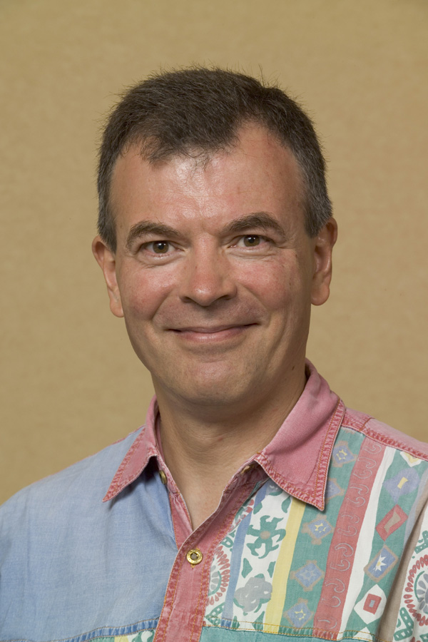
Brian Foster, European regional director for the GDE. (Credit: Jack Liebeck) |
||
 |
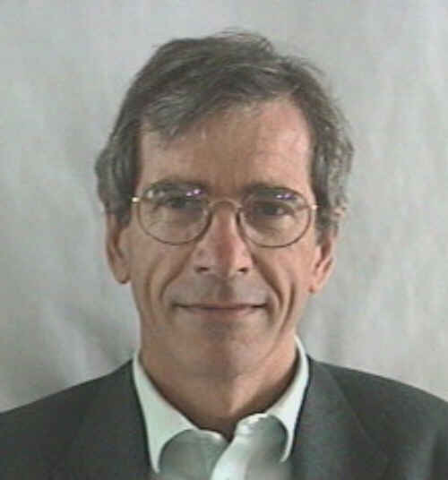
Gerald Dugan, North American regional director for the ILC Global Design Effort. (Courtesy of Fermilab Visual Media Services) |
||
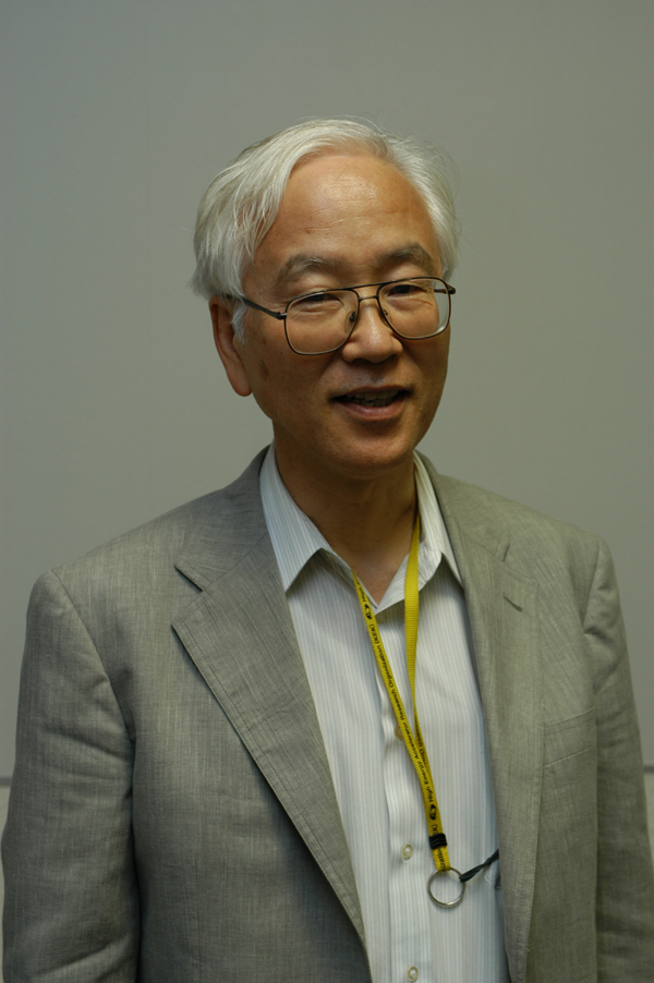 |
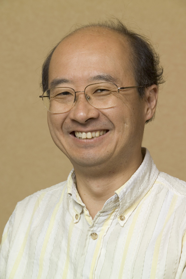
Fumihiko Takasaki, GDE regional director for Asia. (Credit: KEK) |
||
 |
ILC Global Design Effort member Jean-Luc Baldy. |
||
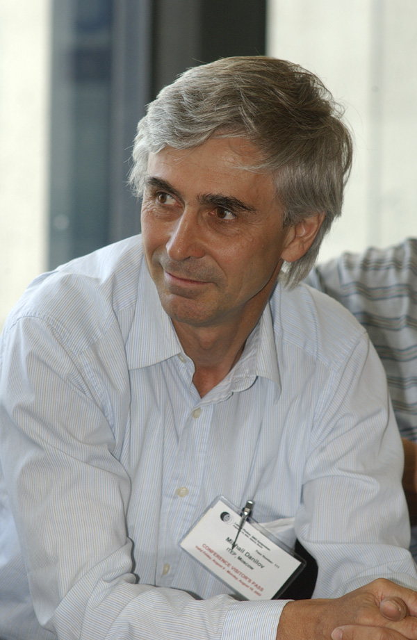 |
ILC Global Design Effort member Michael Danilov. |
||
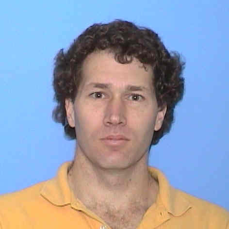 |
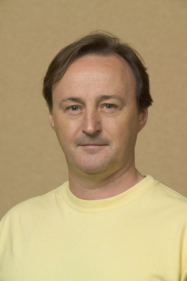
ILC Global Design Effort member Tor Raubenheimer. |
||
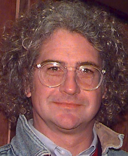 |
ILC Global Design Effort member John Sheppard. |
||
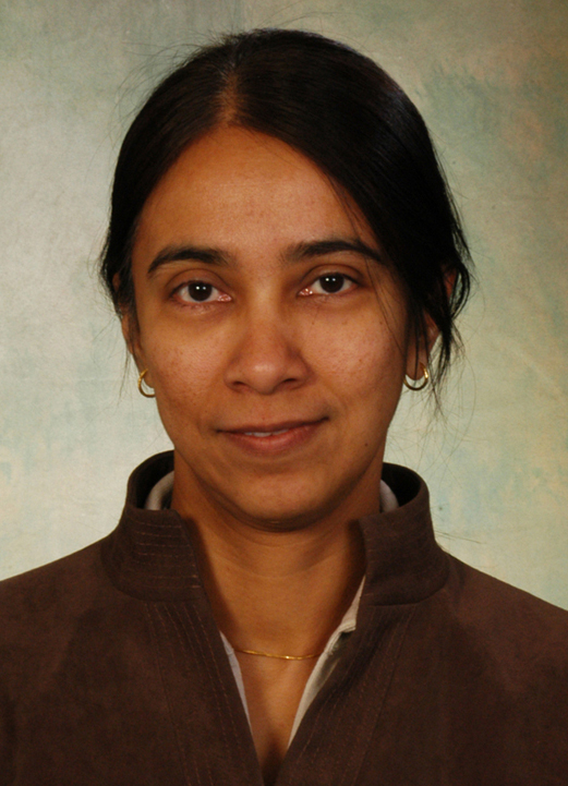 |
ILC Global Design Effort member Deepa Angal-Kalinin. |
||
 |
Illustration includes artists’s renderings for the international linear collider. (Illustration: Symmetry Magazine Courtesy of KEK and Rey, Hori) |
||
 |
Illustration includes artists’s renderings for the international linear collider. (Illustration: Symmetry Magazine Courtesy of KEK and Rey, Hori) |
||
 |
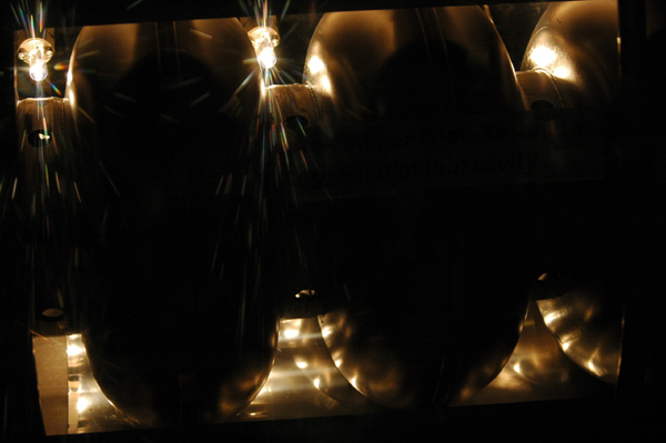
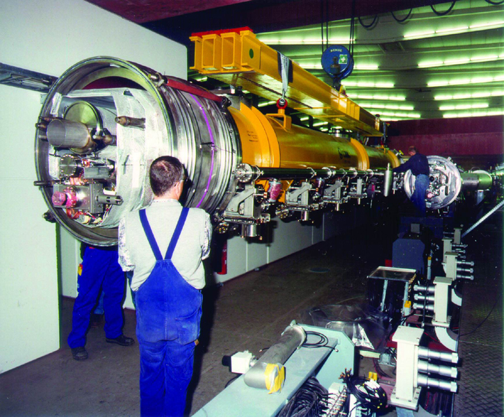
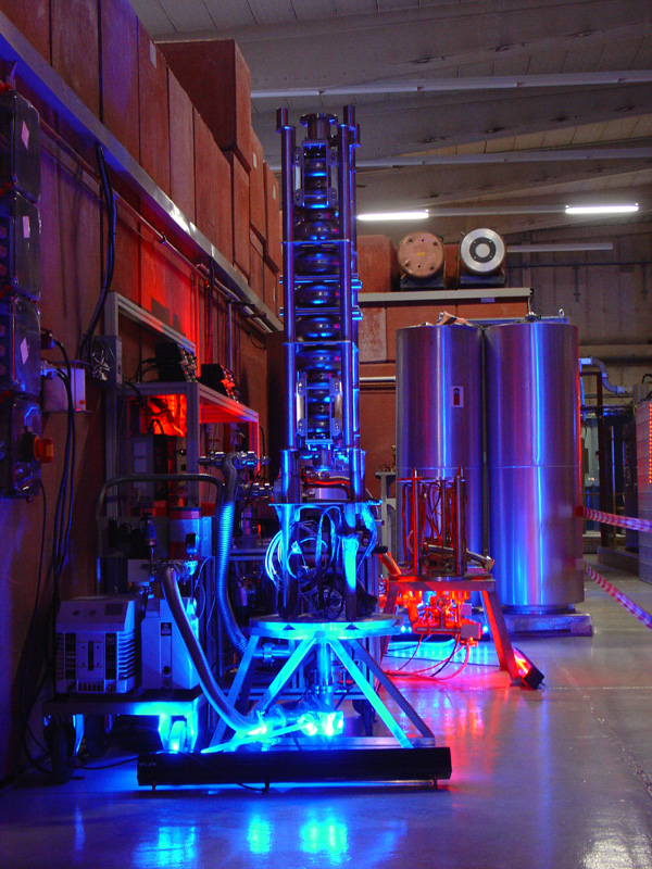
Accelerator module at the TESLA Test Facility at DESY specially illuminated for the first "Science Night" in Hamburg. (Credit DESY) |
||
 |
Accelerator module at the TESLA Test Facility at DESY specially illuminated for the first "Science Night" in Hamburg. (Credit DESY) |
||
 |
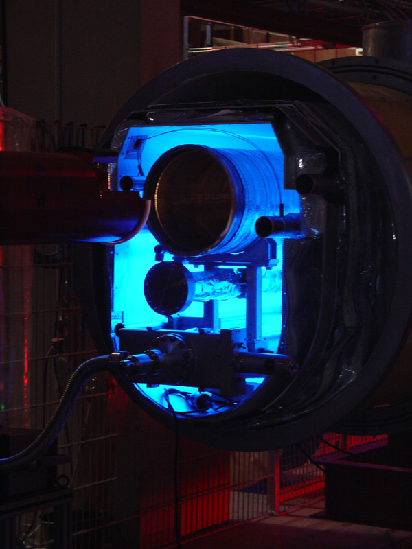
The 120 deg cavity baking station at DESY specially illuminated for the first "Science Night" in Hamburg. (Credit DESY) |
||
 |
Accelerator module at the TESLA Test Facility at DESY specially illuminated for the first "Science Night" in Hamburg. (Credit DESY) |
||
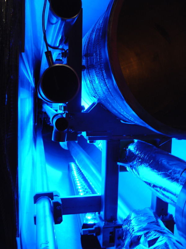 |
Accelerator module at the TESLA Test Facility at DESY specially illuminated for the first "Science Night" in Hamburg. (Credit DESY) |
||
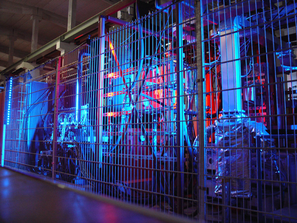 |
Klystron cage at the TESLA Test Facility/VUV-FEL at DESY specially illuminated for the first "Science Night" in Hamburg. (Credit DESY) |
||
 |
Illustration includes artists’s renderings for the international linear collider. (Illustration: Symmetry Magazine Courtesy of KEK and Rey, Hori) |
||
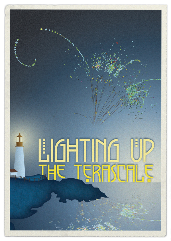 |
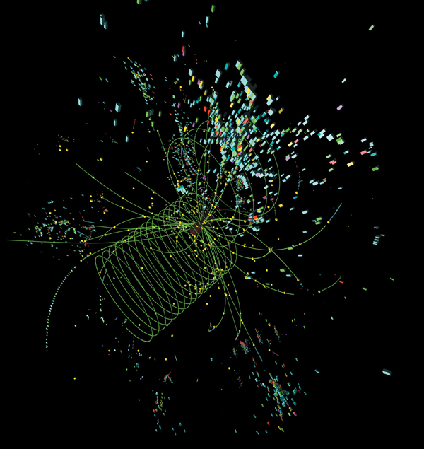
Postcard (Lighting up the Terascale) Particle collisions, like this simulation of a linear collider’s production of a Higgs particle and a Z boson by SLAC physicist Norman Graf, will illuminate the physics of the Terascale. (Credit: Symmetry magazine/Sandbox Studio) |
||
 |
Postcard (Einstein’s Telescope) As a telescope to the beyond, a linear collider would have the potential to see from the Terascale into ultrahigh energy realms where physicists believe all of nature’s forces become one. (Credit: Symmetry magazine/Sandbox Studio) |
||